Introduction
You have a strong, complex part in mind. Laser Sintering (SLS) 3D printing can make it a reality. This process fuses nylon powder with a laser, creating durable parts with no support structures. But to unlock its full power, you must design for it. A good SLS design is strong, precise, and cheap to print. A bad one will warp, trap powder, or fail. This guide gives you the key rules. We cover wall thickness, holes, text, and how to avoid warping. You will learn to design parts that print right the first time.
Why Are SLS Design Rules Unique?
SLS is a powder bed fusion process. A laser draws your part’s shape in a bed of fine plastic powder. The powder around the part acts as natural support. This means you can print amazing shapes. But the powder and heat also create special needs.
What Are the Core Challenges?
Three main issues shape the rules:
- Heat Management: The laser adds intense heat. Thin features can overheat and distort.
- Powder Removal: Unsintered powder must fall out of holes and cavities. If it’s trapped, the part is flawed.
- Cooling Stress: As the whole build cools, large parts can warp or curl from internal stress.
Smart design solves these before you print.
What Are the Key Geometry Rules?
Your part’s shape must work with the powder and laser.
How Thick Should Walls Be?
Wall thickness is critical. Too thin, and the wall collapses or becomes too thick from excess heat. Too thick, and you waste material and money.
| Material | Minimum Wall (Good Result) | Ideal Wall (Strong & Reliable) | Maximum (Before Waste) |
|---|---|---|---|
| Nylon 12 (PA12) | 0.7 mm | 1.2 – 1.5 mm | 5-6 mm |
| Glass-Filled Nylon (PA12-GF) | 1.0 mm | 1.5 – 2.0 mm | 5-6 mm |
| TPU (Flexible) | 1.0 mm | 1.5 – 2.0 mm | 5-6 mm |
Rule: For long, tall walls, add ribs or gussets every 20-30 mm. This prevents bending.
Real Case: A drone frame had 0.6 mm walls to save weight. The parts came out brittle and warped. Changing the wall to 1.2 mm added only 8% weight but made the frame 5x stronger. Print success went from 50% to 99%.
How Do You Design Holes and Channels?
SLS can print holes without drilling. But powder must escape.
- Minimum Hole Diameter: 1.5 mm. Smaller holes trap powder forever.
- Through-Holes vs. Blind Holes: Through-holes are best. For blind holes (dead-end), make the depth no more than 4x the diameter. Deeper holes trap powder at the bottom.
- Internal Channels: For fluid or air paths, make them at least 3 mm in diameter. Add clean-out ports if the path is complex.
Pro Tip: For a press-fit hole (for a bearing or pin), design the hole 0.2-0.3 mm smaller than the part. The SLS nylon has some give for a perfect snug fit.
What About Large Flat Surfaces?
Big, flat areas are a major risk for warping. As the part cools, it pulls inward, curling the edges up.
How to fix it:
- Add Ribs: Put ribs on the back side. Make them 1.0 mm thick and 3-5 mm tall. Space them 15-25 mm apart.
- Dome or Crown It: Slightly curve the surface (even 0.5 mm over 100 mm). This adds stiffness.
- Add a Perimeter Frame: A raised edge around the flat area acts as a stiffener.
Example: A speaker grille (150mm x 150mm flat panel) warped badly. Adding a 1mm rib grid on the back stopped the warp. The part stayed flat.
Can You Make Hollow Parts?
Yes, and it saves a lot of material. But you must add powder escape holes.
- Escape Hole Size: At least 2 holes of 3-4 mm diameter.
- Placement: Put holes at the lowest points when the part is in the printer. Also, put them where they won’t be seen in the final use.
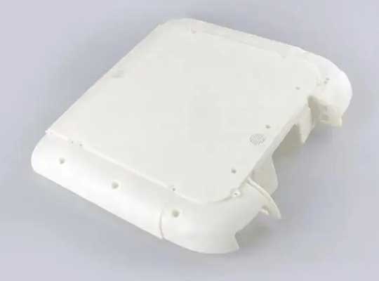
Case: A camera housing was printed solid, using 450 grams of powder. The redesign was hollow with 3mm walls and two vent holes. It used 180 grams, cut cost by 60%, and was just as strong.
How Do You Handle Moving Parts and Assemblies?
This is SLS magic. You can print hinges, chains, and gears already assembled.
What Clearance is Needed?
Parts must move freely but not have powder jam them.
- Clearance for Moving Parts: 0.5 mm minimum between surfaces. For rotating gears, use 0.5-0.7 mm.
- Hinge Pin and Hole: Make the hole 0.3-0.4 mm larger than the pin. This gives smooth motion after powder is blown out.
Real Example: A toy company printed a working wrench and socket as one piece. The socket was trapped inside a cage. They used 0.6 mm clearance all around. After powder removal, the socket spun freely inside. No assembly was needed.
Can You Print Interlocking Parts?
Yes, like a 3D puzzle. The key is generous clearance for powder to flow out.
- Use 0.7-1.0 mm gap between interlocking features.
- Avoid long, thin snap-fits. They can be brittle in nylon. Use living hinges instead for flexible connections.
What About Text and Surface Details?
You can engrave text or logos directly onto the part.
How to Make Good Text?
- Emboss (Raised Text): Make letters at least 1.0 mm tall and 0.8 mm thick. Use a sans-serif font like Arial. Serif fonts have tiny details that break off.
- Engrave (Sunken Text): Make grooves at least 0.5 mm deep and 0.8 mm wide.
- Size Rule: Text should be 5 mm or taller for easy reading after the part’s grainy surface is smoothed.
Pro Tip: Put text on a slightly raised panel. This protects it during the tumbling process that cleans parts.
How Do You Manage Tolerances and Fit?
SLS is accurate, but not perfect. You must plan for small size changes.
What Are Realistic Tolerances?
- Standard Tolerance: ± 0.3% of dimension (with a minimum of ± 0.3 mm). A 100 mm part could be 99.7 to 100.3 mm.
- Critical Fit Tolerance: For parts that must fit together, design with 0.2-0.3 mm intentional gap. This ensures they will fit after printing.
- Hole Shrinkage: Holes often print 0.1-0.2 mm smaller than designed. Compensate by making holes slightly larger in your CAD model.
How to Design for Press-Fits and Snap-Fits?
- Press-Fit Pegs: Make the peg 0.2-0.25 mm larger than the hole. The nylon will compress.
- Cantilever Snap-Fits: Make the snap arm long and thin for more flex. The engagement height should be at least 0.5 mm.
What Are the Size Limits?
Know your printer’s build volume.
- Common Industrial Machine: 300 x 300 x 300 mm (12 x 12 x 12 inches).
- Large Format Machine: Up to 550 x 550 x 750 mm.
- Minimum Feature Size: Reliably, 0.8 mm. You can try 0.5 mm, but it may not print every time.
If your part is too big, split it. Design alignment pins and sockets into the split faces for easy gluing.
How Can You Reduce Cost?
SLS cost is driven by part volume, height, and machine time.
Top Cost-Saving Tips:
- Nest Parts Efficiently: When printing many parts, pack them tightly in the 3D build volume. They can even overlap in the Z-axis because powder supports them.
- Hollow Parts: As discussed, this is the #1 save.
- Reduce Height: A tall part uses more powder and more laser passes. Can you lay it on its side?
- Use Less Material: Thinner walls (within the safe range) use less powder.
Case Study: A client needed 50 cable clips. The first design was a solid block (15 grams each). The redesign was a hollow shell with ribs (6 grams each). This cut the powder bill by 60% and made the parts lighter for shipping.
What Post-Processing Should You Plan For?
SLS parts come out grainy and dusty. Think ahead.
- Surface Finish: The raw finish is like fine sandpaper. For a smooth feel, you can media tumble (vibrate with abrasive media) or smooth with a coating.
- Strength: SLS parts are strong but can be porous. For water-tight or extra strong parts, use an impregnation sealant.
- Color: Raw nylon is white or gray. You can dye parts in a bath to many colors.
Conclusion
Designing for SLS 3D printing is about respecting the process. Use walls thicker than 0.7 mm. Make holes larger than 1.5 mm. Avoid large flat areas or reinforce them with ribs. For moving assemblies, use 0.5 mm clearances. Remember to add escape holes to hollow parts. By following these rules, you use SLS’s full power: making strong, complex, functional parts in a single print run. Test your design with a small print first. Then scale up with confidence.
FAQ
What is the smallest text I can print on an SLS part?
For text to be clear after tumbling, use 2 mm tall letters as a minimum. For very fine serial numbers, 1 mm is possible but may wear down during cleaning. Always use a bold, sans-serif font.
Can SLS print overhangs?
Yes, and very well. SLS can print overhangs up to 90 degrees (horizontal) without supports because the unsintered powder holds it up. However, the underside surface will be rougher where it contacts loose powder.
Why does my SLS part feel gritty?
The powder-based process leaves a semi-fused layer of particles on the surface. This is normal. For a smooth feel, you need post-processing like media tumbling, sanding, or a smoothing coat.
Is it cheaper to print many small parts at once?
Yes, this is a key SLS benefit. The cost is mainly for the full build volume, not per part. Filling the build chamber with many parts spreads the fixed cost, making each part very cheap.
How strong is SLS nylon compared to injection molded nylon?
SLS Nylon 12 is about 80-90% as strong as injection molded Nylon 12. It is isotropic (equally strong in all directions), which is better than FDM prints. It is fully suitable for functional, load-bearing parts.
Discuss Your Projects with Yigu Rapid Prototyping
At Yigu, SLS is a core service. Our engineers review designs daily to optimize for print success and cost. We use industrial Farsoon and EOS machines for high-quality nylon parts. For a recent client, we redesigned a complex duct assembly from 8 assembled pieces to 1 SLS part, cutting assembly time and improving airflow. We also offer full post-processing like media tumbling and dyeing. If you have a part that needs the strength and complexity of SLS, send us your design. We’ll provide a free design review and quote to help you get the best result.