Introduction
If you are deep in the process of developing a new product, you have likely reached that critical point where your design needs to leave the computer screen. You need something real. You need a machining prototype. So, what exactly is it? Simply put, a machining prototype is a physical, functional part created by removing material from a solid block—often called a “blank”—using processes like milling, turning, or drilling. Think of it as precision carving guided by your digital design. This is subtractive manufacturing, which is quite different from 3D printing that builds parts layer by layer. The entire purpose of creating a prototype this way is to validate your product’s form, fit, and function long before you commit to the high costs of mass production. I once advised a team building a new kind of electric bicycle motor. Their very first machined prototype revealed a cooling fin design that was completely ineffective. Catching that flaw early saved them months of redesign and a huge amount of money. That is the real power of getting it right.
What Are the Core Machining Processes for Prototypes?
Choosing the correct starting process is your first big decision. Each method shapes material in a unique way and is suited for different types of parts.
CNC Milling: For Complex Shapes and Features
CNC milling uses rotating cutting tools to carve out a part from a stationary block of material. The “CNC” stands for Computer Numerical Control, which means the whole process is automated with high precision. It is the most versatile process and is perfect for parts with flat surfaces, pockets, slots, ribs, and precise holes.
- Best Applications: Housings for electronics, brackets, engine components, and parts with complex 3D surfaces.
- Real-World Example: A few years ago, a client needed a prototype for a new robotic arm joint. The part had to be light but strong, with several curved surfaces and precise mounting points for servos. We used CNC milling on a block of 7075 aluminum. Within three days, they had a part in their hands. They immediately saw that one of the mounting bosses was slightly too close to the arm’s movement path. They updated the CAD file, and we machined a corrected version in another 48 hours. This rapid iteration was only possible because milling provided a part that was strong enough for real movement tests.
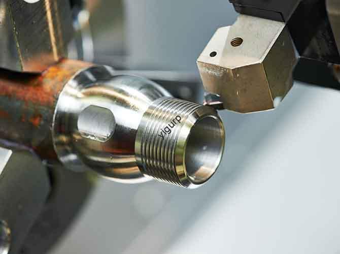
CNC Turning: The King of Cylindrical Parts
If your part is round, CNC turning is usually your best and fastest option. In this process, the material blank spins at high speed while a stationary cutting tool moves along it, shaving off material to create the desired shape. It is incredibly efficient for parts that need to be perfectly concentric.
- Best Applications: Shafts, rollers, pulleys, bushings, and threaded fasteners.
- Key Data Point: Modern CNC lathes can achieve exceptional precision. For prototypes, you can expect tolerances in the range of ±0.0005 inches (0.013 mm) . This level of accuracy is non-negotiable when your part needs to fit inside a bearing or seal against another component.
Drilling and Tapping: Creating Holes and Threads
These are often secondary operations but are absolutely critical for assembly. Drilling creates the hole, and tapping cuts the internal threads for a screw or bolt. While a mill can also do these tasks, dedicated drilling/tapping can be faster for simple parts.
- Best Applications: Any part that will be assembled with others, such as flanges, covers, and panels.
- Practical Insight: I worked with a furniture startup on a prototype for a modular shelving connector. The design required several precisely tapped holes to join different sections. If the tapping was even slightly off, the whole connector would be useless. By specifying the tap size and depth clearly on the drawing, we got a prototype that screwed together perfectly on the first try.
How to Pick the Perfect Material for Your Prototype?
The material you choose directly affects the cost, strength, and validity of your tests. Your goal should be to match the properties of your final production material as closely as possible.
| Material | Key Properties | Best Use Cases | Common Trade-offs |
|---|---|---|---|
| Aluminum (6061 or 7075) | Lightweight, good strength, excellent machinability, corrosion-resistant. | Aerospace brackets, drone parts, consumer electronics enclosures. | Can be more expensive than some plastics; not as strong as steel for heavy loads. |
| Steel (1018 or 4140) | Very strong, durable, excellent for high-stress applications. | Gears, load-bearing industrial parts, tooling fixtures. | Heavy; can be slow to machine; higher cost than aluminum. |
| Stainless Steel (304 or 316) | Strong, excellent corrosion resistance, good for sterile environments. | Medical devices, food processing equipment, marine hardware. | Can be difficult to machine (work hardens); more expensive than carbon steel. |
| Acetal (Delrin) | Low friction, high stiffness, good dimensional stability, resists moisture. | Gears, bushings, jigs, fixtures, pump parts. | Not suitable for very high temperatures; not as strong as metal. |
| Titanium (Grade 5) | Highest strength-to-weight ratio, biocompatible, extreme corrosion resistance. | Medical implants, aerospace components, high-performance racing parts. | Very expensive; difficult and slow to machine; requires specialized tooling. |
- Case in Point: A medical startup needed a prototype for a new surgical retractor. They first asked for an aluminum version to save money. When tested, the aluminum prototype bent under the required pressure. We recommended switching to stainless steel 316L for the next iteration. It cost more and took a little longer to machine, but it held up perfectly during surgical simulations. This material change was essential for validating the design’s real-world viability.
A Simple, Step-by-Step Plan to Create Your Prototype
Getting a successful machining prototype is a process. Following these steps will help you avoid common and costly mistakes.
Step 1: Lock Down Your 3D CAD Model
This is your blueprint. You need a complete and detailed 3D CAD file, typically created in software like SolidWorks, Fusion 360, or AutoCAD. This file must include all critical dimensions and clearly note which tolerances are important.
- Pro Tip: Before sending the file, check for things like sharp internal corners. A milling cutter has a round shape, so it cannot cut a perfect 90-degree inside corner. You need to add a small fillet (radius) in your design. I once had a client whose part design had razor-sharp corners. We pointed this out, they added a 0.5mm radius, and the part machined perfectly without any stress cracks.
Step 2: Match the Process to Your Part
Look at your part’s geometry. Is it a box with holes? That points to milling. Is it a long cylinder with a groove? That points to turning. Does it have both? You might need a part that is milled and then turned, or vice versa. Talk to your machine shop about the most efficient approach.
Step 3: Find the Right Machining Partner
You are not just looking for someone with machines. You are looking for a partner with the right expertise.
- Look For:
- Experience: Do they have a track record with your chosen material? Ask for examples.
- Capability: Do they use modern CNC equipment? This ensures precision and speed.
- Communication: Do they ask good questions about your design? This is a sign of a partner who wants to help you succeed.
- A Cautionary Tale: A client once chose a shop solely based on a low quote. The shop used old, manual machines. The resulting prototype was 0.02 inches out of spec and completely useless. Switching to a CNC-focused prototyping service fixed the problem immediately.
Step 4: Perform a Thorough First Article Inspection
When you receive the prototype, your job is not done. You must test it rigorously.
- Fit: Assemble it with any mating parts. Does everything line up?
- Form: Check the critical dimensions with calipers. Does it match your CAD file?
- Function: Test it in its intended environment. Does a shaft spin freely? Does a bracket hold the expected weight?
- Example: For a drone motor mount prototype, the client immediately tried attaching the motor. They found the screw holes were 0.1mm too close together. Because they caught it right away, we could quickly machine a corrected version.
Step 5: Iterate to Perfection
Almost no prototype is perfect on the first run. Plan for 1 to 3 iterations. Use what you learn from testing each version to refine the design. This cycle of build-test-learn is how great products are made.
Machining Prototype vs. 3D Printing: A Clear Comparison
This is a common fork in the road. Both technologies create parts, but they serve different purposes. Here is how to choose.
| Feature | Machining Prototype | 3D Printed Prototype |
|---|---|---|
| Material Authenticity | High: Uses real production materials (solid metals, engineering plastics). | Low: Mostly uses proprietary resins or powders with different properties. |
| Part Strength | Production-like: Parts are solid and isotropic, ideal for functional stress tests. | Variable: Layer adhesion can be a weak point. Good for visual models. |
| Precision & Tolerance | Excellent: Can achieve tight tolerances down to ±0.0005 inches. | Good: Typical tolerances are looser, around ±0.005 to 0.020 inches. |
| Surface Finish | Smooth: Clean machined surfaces. Can be easily polished or coated. | Textured: Has visible layer lines. Requires post-processing to smooth. |
| Cost for 1-10 Parts | More cost-effective per part as quantity increases. Setup cost is spread out. | Very cheap for a single part, but cost per part stays high. |
| Best For | Functional testing, fit checks, parts that need to be strong, metal parts. | Visual aids, early concept models, complex organic shapes. |
The Simple Rule: Use 3D printing for early design concept models. Use machining when you need to be sure your part will actually work in the real world.
Five Common Mistakes That Ruin Prototypes (And How to Avoid Them)
After years in this field, I see the same issues pop up again and again. Here is how to steer clear of them.
Mistake 1: Not Defining Tolerances
If you don’t tell the machinist how precise a hole needs to be, they will use a standard shop tolerance. That might be too loose for a critical fit.
- Fix: On your drawing, clearly mark which dimensions are critical with the required tolerance, for example, “+0.000/-0.002 inches.”
Mistake 2: Designing Features That Can’t Be Machined
Designing a deep pocket with a very small width is a classic error. The tool needed to reach the bottom might be too long and thin, and it will vibrate or break.
- Fix: Talk to your machining partner early. They can advise on minimum tool sizes and achievable depths for your design.
Mistake 3: Sacrificing Material Properties for Cost
Using a cheap plastic to prototype a part that will eventually be made from die-cast aluminum can give you misleading test results.
- Fix: Spend the money to prototype in a material that closely mimics the mechanical properties of your final production material. It is a worthwhile investment.
Mistake 4: Forgetting About the Machine’s Reach
Your CNC machine has limits. It cannot cut every surface from every angle. If a feature is hidden behind another, it might be impossible to reach with a cutting tool.
- Fix: This is another reason to collaborate. An experienced shop will identify these “unreachable areas” and suggest design modifications or a different part orientation.
Mistake 5: Rushing the Inspection
It is exciting to get your part. But don’t let that excitement stop you from a careful inspection.
- Fix: Schedule time for testing the moment you receive the prototype. A client once skipped this and presented the part to their investors, only to discover during the demo that a critical slider mechanism was stuck.
Conclusion
Creating a successful product is a journey filled with important decisions. Choosing to build a machining prototype is one of the smartest moves you can make. It is the most reliable way to pull your design out of the digital world and see how it performs under real-world conditions. By using processes like CNC milling and turning with the right materials, you gain invaluable knowledge about your part’s strength, precision, and manufacturability. It allows you to test, fail, learn, and iterate cheaply and quickly. The small upfront investment in a machined prototype is the best insurance policy you can buy against the massive costs and delays of a production run gone wrong. In the end, getting your prototype right isn’t just about making a part; it’s about building the confidence to move forward.
FAQ About Machining Prototypes
1. How much should I budget for a machining prototype?
Costs are highly variable. A simple aluminum part the size of a smartphone might cost $150 to $400. A complex, multi-axis titanium part could be $800 to $2,500 or more. The best approach is to get a quote based on your final CAD file.
2. What is the typical turnaround time for a machined prototype?
For most projects with a standard level of complexity, you can expect a part in 3 to 7 business days. Simple, cylindrical parts made by turning might be done in 1-2 days. Rush services are often available for an additional fee.
3. What file format does a machine shop need?
The industry standard is the STEP file format (.stp or .step) . It reliably transfers the complete 3D geometry between different software programs. Other acceptable formats include IGES (.igs) or Parasolid (.x_t). Always confirm with your chosen shop.
4. Can you machine a prototype from a 3D printed model?
No, you cannot machine a 3D printed model. Machining is a subtractive process that starts with a solid block. However, you can use a 3D printed part as a visual reference or for a very rough fit check before committing to the time and cost of machining a functional prototype.
5. My part is very complex. Is machining still an option?
Often, yes, but it may require breaking the design into multiple parts that are machined separately and then assembled. A good machining partner can help you analyze your complex design and figure out the most practical and cost-effective way to create a functional prototype.
Discuss Your Projects with Yigu Rapid Prototyping
At Yigu Rapid Prototyping, we know that your machining prototype is a pivotal moment for your entire project. It is the bridge between a great idea and a market-ready product. We combine deep engineering experience with a full suite of advanced capabilities, including high-speed CNC milling, precision turning, and expert finishing. We don’t just run machines; we collaborate with you. Our team will review your design, flag potential issues like unreachable features or unrealistic tolerances, and offer practical solutions to make your part both manufacturable and true to your vision. We are committed to complete transparency, providing clear communication and thorough quality checks every step of the way. Whether you need one critical component for a medical trial or a small batch of complex parts for field testing, we are here to help you succeed. Contact Yigu today to discuss your project and get a free, no-obligation quote.