Form cutter milling is a go-to precision machining method for anyone needing custom, complex-shaped parts—from aerospace engineers to small-shop machinists. Unlike basic milling that makes simple slots or flat surfaces, form milling uses a cutter with a pre-shaped profile that matches the exact contour you want on your workpiece. This means you can make parts like gear teeth, splined shafts, or custom curved turbine blades in fewer steps, with tighter accuracy. In this guide, we’ll break down everything you need to know: what form cutter milling really is, how it works in real shops, the best cutters to choose, common problems and fixes, and how different industries use it daily. By the end, you’ll have practical, actionable tips to use this process effectively for your own projects, whether you’re making 10 prototype parts or 10,000 production pieces.
What Exactly Is Form Milling?
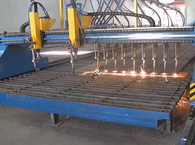
At its core, form cutter milling is a subtractive manufacturing process. That just means it removes material from a workpiece to get the shape you want—but what makes it unique is the form cutter itself. This cutter isn’t a generic tool; its edges are ground or shaped to replicate the exact profile of the final part. Think of it like a cookie cutter: the cutter’s shape transfers directly to the dough (or in this case, the metal, plastic, or composite workpiece).
Unlike standard end milling, which uses a cylindrical cutter to make simple shapes, form milling excels at complex, non-linear geometries. These are shapes that would take hours (or be impossible) to make with regular tools—things like the teeth on a spur gear, the curves on a camshaft lobe, or the intricate airfoil of a turbine blade. The key here is precision: form milling is designed to make parts that match tight design specs, often within thousandths of an inch.
Let’s look at a real-world example: A local lawnmower repair shop needed to replace worn gear teeth on a vintage lawnmower transmission. The gears were no longer made by the manufacturer, so they turned to form cutter milling. A machinist created a custom form cutter with the exact 14.5° pressure angle and tooth profile of the original gear. Using a small CNC mill, they machined a new gear from low-carbon steel—matching the original’s dimensions so perfectly that the lawnmower ran like new again. This is the power of form milling: it solves problems where off-the-shelf parts or basic machining won’t cut it.
Why Use Form Milling?
What’s Its Main Purpose?
The number one goal of form cutter milling is to efficiently make complex, custom profiles with high accuracy and repeatability. But let’s break down the specific reasons why machinists and manufacturers choose it over other methods:
- Complex Shape Replication: It’s the only practical way to make parts with intricate contours—like the curved surfaces of a medical spinal implant or the splines on an automotive transmission shaft—that can’t be replicated with standard tools.
- Production Efficiency: Instead of using 5 or 6 different generic cutters to shape a part, you use one form cutter. This cuts down on setup time, tool changes, and labor—saving both time and money, especially for high-volume runs.
- Tolerance Control: For critical parts (like those used in airplanes or medical devices), even tiny deviations can cause failure. Form milling achieves micron-level tolerances (as tight as ±0.0005 inches), ensuring every part matches the design exactly.
- Cost Savings (Long-Term): While custom form cutters are expensive upfront, they reduce per-part costs for high-volume production by cutting down on machining steps, scrap, and post-processing.
A great example of this comes from an automotive supplier near Detroit. They used to make camshafts for diesel engines using 4 different tools: one to rough out the lobe shape, two to refine the curves, and one to smooth the surface. This took 15 minutes per camshaft, with a scrap rate of 8% (parts that didn’t meet tolerance). When they switched to form cutter milling, they used one custom cutter that shaped the lobe in two passes. Production time dropped to 5 minutes per part, and scrap rates plummeted to 1.2%. Over a year, this saved them over $200,000 in labor and material costs.
How Does Form Milling Work?
What Are the Core Mechanics?
Form milling is simple in concept, but it relies on precise coordination between the cutter, the workpiece, and the milling machine. Here’s a step-by-step breakdown of how it works in a typical shop:
First, the form cutter is mounted on the spindle of a CNC milling machine. The spindle spins the cutter at high speeds—usually between 500 and 10,000 RPM, depending on the cutter material and the workpiece. Next, the workpiece is secured in a fixture (a clamp or holder) that keeps it stable during machining. The CNC machine’s computer controls the movement of either the workpiece or the cutter (or both) along linear or rotational axes.
The magic happens when the spinning form cutter makes contact with the workpiece. As the cutter rotates, its pre-shaped profile removes material, transferring its shape to the workpiece. Unlike plunge milling (where the cutter dives straight down into the material), form milling usually uses peripheral cutting—the side of the cutter does the work, not the end face. This ensures the full profile of the cutter is transferred evenly.
Let’s take a concrete example: Machining a splined shaft for a small tractor. A splined shaft has evenly spaced teeth along its length that fit into a mating part to transmit torque. The form cutter for this job has a profile that matches the shape of the space between two spline teeth. The CNC machine spins the cutter at 3,500 RPM and feeds the shaft axially (along the cutter’s axis) while rotating it incrementally. Each rotation of the shaft positions a new space for the cutter to shape, resulting in uniform, precise splines that fit perfectly with the mating component. The final tolerance here is ±0.0008 inches—so small you’d need a microscope to see the difference between the machined part and the design.
What Movements Make It Work?
Three core movements, coordinated by the CNC machine, are essential for successful form milling. Without these working together, you’ll get inaccurate parts, worn cutters, or even damage to the machine:
- Cutter Rotation: This is the primary movement—the cutter spins around its own axis (spindle rotation) to generate the cutting force. The speed (RPM) depends on three things: cutter material, workpiece material, and profile complexity. For example, a carbide form cutter machining steel runs at 3,000–5,000 RPM, while the same cutter on aluminum (a softer material) runs at 8,000–10,000 RPM. If you run a cutter too fast, it overheats and wears out; too slow, and you get a rough surface finish.
- Feed Movement: This is the movement of the workpiece or cutter relative to the spinning cutter. There are three common types: axial (along the cutter’s axis), radial (perpendicular to the axis), and contour (following a curved path). For gear teeth, you’d use radial feed—the cutter moves into the workpiece to the correct depth, then the workpiece rotates to cut each tooth. For complex 3D shapes (like turbine blades), you use helical interpolation—a combination of feed and rotation that creates smooth, consistent material removal.
- Depth of Cut: This is how far the cutter penetrates the workpiece, controlled by the machine’s Z-axis. It’s critical for accuracy: too deep, and the cutter bends (called deflection) or damages the workpiece; too shallow, and you need extra passes, wasting time. For hard materials like titanium, the depth of cut is limited to 0.005–0.010 inches per pass to protect the cutter.
Pro Tip: If you’re machining a complex 3D profile (like a turbine blade airfoil), use helical interpolation. This coordinated movement ensures the cutter stays in contact with the workpiece at the right angle and speed, resulting in a smooth surface finish that needs minimal post-processing.
What’s the Typical Form Milling Workflow?
Most shops follow a standard 8-step process for form cutter milling, especially for high-volume production or critical parts. This workflow ensures consistency, reduces scrap, and makes sure every part meets the design specs. Here’s how it works, with a real example from a medical device shop:
| Step | Action | Key Considerations |
|---|---|---|
| 1 | Design & Cutter Fabrication | Create a CAD model of the desired profile; make a form cutter to match (grind for production, 3D print for prototypes). |
| 2 | Workpiece Preparation | Cut raw material to size; remove burrs; heat treat if needed (e.g., harden steel gears). |
| 3 | Machine Setup | Mount the form cutter to the spindle; secure the workpiece in a fixture; calibrate tool offsets and axis alignment. |
| 4 | Test Run | Machine a prototype part; inspect profile, dimensions, and surface finish to check the setup. |
| 5 | Parameter Adjustment | Tweak RPM, feed rate, or depth of cut if the test part fails (e.g., adjust feed to reduce vibration). |
| 6 | Production Run | Start full production; monitor cutter wear and profile accuracy while machining. |
| 7 | Post-Processing | Deburr, polish (if needed), and heat treat (after machining) for final part properties. |
| 8 | Quality Inspection | Verify dimensions with a CMM; check surface finish with a profilometer; confirm profile matches the CAD model. |
Real-World Example: A medical device manufacturer in Minnesota uses this workflow to make titanium spinal implants with a custom curved profile. The test run step is critical here—any mistake could lead to implant failure, so they inspect 3 prototype parts with a 0.5-micron CMM (Coordinate Measuring Machine) before starting production. The CMM uses a tiny probe to map the part’s surface, comparing it to the CAD model with extreme precision. If even one prototype is off by 0.0001 inches, they adjust the machine and test again. This attention to detail ensures their implants meet FDA standards and are safe for patients.
What Types of Form Milling Cutters Exist?
How Are They Classified?
Form milling cutters are grouped by two main factors: their profile geometry (the shape of their cutting edge) and their construction (the material and design of the cutter). Choosing the right type depends on your part’s shape, workpiece material, and production volume. Let’s break down the most common types:
Geometry-Based Cutter Types
These cutters are designed for specific part shapes—each one is tailored to a particular contour or feature:
- Gear Cutters: Ground to match gear tooth profiles (spur, helical, bevel). They’re used in automotive and industrial gearboxes. A common example is a 14.5° pressure angle gear cutter for the spur gears in a lawnmower transmission or a 20° pressure angle cutter for automotive transmission gears.
- Spline Cutters: Used to make splined shafts (internal or external) that transmit torque. They’re common in aerospace and heavy machinery. The key specs here are the number of splines (e.g., 6-spline, 12-spline) and the tooth width.
- Contour Cutters: For custom curved profiles, like turbine blades, camshaft lobes, or medical implants. They can be 2D (simple curves, like a semicircle) or 3D (complex shapes, like a turbine blade airfoil).
- Groove Cutters: Make precision grooves, slots, or keyways with specific widths and depths. They’re used in shafts, pulleys, and bearings. An example is a 0.125-inch wide groove cutter for keyways in an automotive crankshaft.
- Thread Mills: A subset of form cutters that create internal or external threads (e.g., UNC, metric). They’re ideal for large-diameter threads in aerospace components, where tapping (another thread-making method) would be too slow or inaccurate.
Construction-Based Cutter Types
The way a cutter is made affects its durability, cost, and best uses. Here’s a breakdown of the most common construction types, with pros and cons for each:
| Cutter Type | Construction Details | Best Applications | Pros & Cons |
|---|---|---|---|
| Solid Carbide | One-piece carbide construction; precision ground profile. | Hard materials (steel, titanium), high-volume runs. | Pros: High wear resistance, tight tolerances. Cons: Expensive; brittle if misused (e.g., hitting a hard spot). |
| HSS (High-Speed Steel) | HSS body; often coated with TiN or TiAlN for wear resistance. | Soft materials (aluminum, brass), low-to-medium volume. | Pros: Affordable, flexible (less brittle than carbide). Cons: Less durable; slower cutting speeds. |
| Inserted Form Cutters | Modular design with replaceable carbide inserts; inserts ground to profile. | Large-diameter cutters, heavy-duty machining. | Pros: Cost-effective (replace inserts, not whole cutter); versatile. Cons: Slightly lower precision than solid cutters. |
| Custom Ground Cutters | Made-to-order profile for unique geometries; solid carbide or HSS. | Prototyping, low-volume custom parts (e.g., medical implants). | Pros: Perfect profile match. Cons: Long lead time (2–4 weeks); high cost for small batches. |
How Are Form Milling Cutters Made?
What Processes Create Them?
Making a form cutter is just as precise as using one. The goal is to create a cutter with a profile that matches the desired part exactly—down to thousandths of an inch. Here are the core steps in form cutter manufacturing, with key details and stats:
- Blank Preparation: Start with a solid bar of carbide, HSS, or tool steel. Cut it to rough size using a saw or CNC lathe. The blank needs to be slightly larger than the final cutter to leave room for grinding.
- Heat Treatment: Harden the blank to improve wear resistance. For HSS, this means heating it to 1,800–2,000°F, quenching it in oil or water (to cool it quickly), and then tempering it (heating it again at a lower temperature) to reduce brittleness. Carbide blanks are sintered—heated under high pressure (up to 20,000 psi) to form a dense, hard material.
- Profile Grinding: This is the most critical step. Use a CNC surface grinder or thread grinder to shape the cutter’s profile. For complex 3D profiles, a 5-axis grinder is used to ensure every part of the profile is accurate. Tolerances here are as tight as ±0.0005 inches—so small that even a tiny mistake would make the cutter useless.
- Flute Machining: Cut flutes (channels) into the cutter to allow chips to escape. The number of flutes depends on the profile complexity: 2–4 flutes for simple shapes, 6+ for complex contours. Wider flutes are better for materials that produce large chips (like aluminum), while narrower flutes work for harder materials (like steel).
- Coating: Apply a wear-resistant coating to extend tool life. Common coatings include TiN (titanium nitride, gold color), TiAlN (titanium aluminum nitride, purple color), and DLC (diamond-like carbon, black color). TiAlN coatings reduce friction and increase heat resistance, making them ideal for steel machining.
- Quality Inspection: Verify the profile with a profile projector or CMM. Check the flute geometry and surface finish. Any cutter with a profile deviation exceeding 0.001 inches is rejected. A key stat from the Precision Grinding Technology Association: Custom form cutters require profile grinding with a resolution of 0.1 microns to meet the tight tolerances of aerospace components.
What Materials Are Used?
The material of the form cutter depends on the workpiece material, production volume, and cost budget. Here are the most common options, with details on their best uses:
- Carbide: The gold standard for high-precision, high-volume applications. It has a hardness of 90–95 HRC (Rockwell Hardness Scale) and is resistant to heat and wear. It’s used for machining steel, titanium, and other hard materials. According to Aerospace Manufacturing Magazine, carbide accounts for 65% of form cutters used in aerospace manufacturing.
- HSS (High-Speed Steel): Affordable and flexible, with a hardness of 60–65 HRC. It’s suitable for aluminum, brass, and low-carbon steel. It’s a good choice for small-batch runs or prototype cutters, where the upfront cost of carbide is too high.
- Cobalt HSS: HSS alloyed with 5–8% cobalt for improved heat resistance. It’s used for machining stainless steel and cast iron. It offers 2x longer tool life than standard HSS.
- Cermets: Ceramic-metal composites (titanium carbide + nickel/cobalt). They’re harder than carbide and used for high-speed machining of hardened steel (up to 60 HRC). Pros: High wear resistance. Cons: Brittle, so they require a rigid machine to prevent chipping.
- Diamond-Coated Carbide: For machining non-ferrous materials (aluminum, composites). The diamond coating reduces friction and prevents chip buildup. It extends tool life by 5–10x compared to uncoated carbide.
How to Choose the Right Form Cutter?
What Factors Matter Most?
Choosing the wrong form cutter can lead to costly problems: poor surface finish, dimensional errors, cutter failure, and high scrap rates. To get it right, you need to balance 6 key factors. Let’s break them down, with common mistakes to avoid:
- Workpiece Material: Match the cutter material to the workpiece’s hardness. For example, use carbide for hardened steel (≥45 HRC) and HSS for aluminum. A common mistake: Using HSS cutters on titanium. This leads to rapid wear (the cutter can wear out after just 100 parts) and a rough surface finish.
- Profile Complexity: Simple profiles (e.g., straight grooves) can use standard cutters. Complex 3D profiles (e.g., turbine blades) require custom ground carbide cutters. If you try to use a standard cutter for a complex profile, you’ll end up with inaccurate parts.
- Production Volume: High-volume runs (10k+ parts) benefit from solid carbide cutters—they last longer, reducing tool changes and downtime. Low-volume/prototyping can use HSS or inserted cutters, which have a lower upfront cost. Using a custom solid carbide cutter for a 50-part prototype run is a waste of money.
- Tolerance Requirements: Tight tolerances (±0.0005 inches) demand solid carbide cutters with precision grinding. Looser tolerances (±0.005 inches) can use inserted cutters. If you use an inserted cutter for a tight-tolerance part, the slight play in the inserts will cause dimensional errors.
- Machining Conditions: High-speed machining requires heat-resistant cutters (cermets, diamond-coated carbide). Heavy-duty cutting needs rigid inserted cutters. If you use a brittle carbide cutter for heavy-duty machining, it will chip or break.
- Cost Budget: Custom solid carbide cutters cost $200–$1,000+. HSS cutters cost $50–$200. Remember: Carbide may cost more upfront, but it reduces total cost per part for high volumes. For example, a $500 carbide cutter that lasts 10,000 parts costs $0.05 per part, while a $100 HSS cutter that lasts 1,000 parts costs $0.10 per part.
Why Is Correct Selection Critical?
Choosing the right cutter isn’t just about saving money—it’s about ensuring your parts are safe, compliant, and functional. Here’s a real horror story from an aerospace manufacturer: They used an HSS form cutter to machine titanium turbine blades for a commercial airplane. The HSS cutter wore out quickly, leading to 30% scrap (parts that didn’t meet tolerance). This caused a $50,000 production delay, and they had to rework hundreds of parts. When they switched to diamond-coated carbide cutters, scrap rates dropped to 0.5%, and cycle time decreased by 25%. The cost of the new cutters was negligible compared to the savings from reduced scrap and downtime.
Another example: In medical manufacturing, using a non-biocompatible cutter material (like uncoated carbide) can contaminate implants, leading to FDA rejection. For automotive gear production, using a cutter with the wrong pressure angle causes gear meshing issues, leading to warranty claims and safety risks. Correct cutter selection ensures compliance with industry standards and keeps your parts reliable.
How Does Form Milling Compare to Other Methods?
Form cutter milling is one of several precision milling methods, but it’s not the best choice for every job. Below is a head-to-head comparison of form milling with other common methods, so you can choose the right one for your project:
| Process | Accuracy (Tolerance) | Cycle Time (Per Part) | Best For | Cost Per Part (10k Run) |
|---|---|---|---|---|
| Form Cutter Milling | ±0.0005–±0.002 inches | Short (1–5 minutes) | Complex custom profiles (gears, splines) | $1.20–$3.50 |
| End Milling | ±0.001–±0.005 inches | Long (5–15 minutes) | Simple shapes (slots, pockets) | $0.80–$2.00 |
| Face Milling | ±0.002–±0.008 inches | Fast (30 sec–2 minutes) | Flat surfaces (workpiece faces) | $0.30–$1.00 |
| CNC Engraving | ±0.0005–±0.001 inches | Very Long (10–30 minutes) | Fine details, shallow profiles | $2.50–$5.00 |
Key Takeaway: Form cutter milling is the best choice when you need complex profiles with high accuracy and speed. End milling is better for simple shapes (like slots), while face milling excels at flat surfaces (like the face of a block). For fine details (like engraved logos), CNC engraving is preferred, but it’s slower and more expensive. If you’re unsure which method to use, ask yourself: Does my part have a complex, custom contour? If yes, form milling is likely the way to go.
Which Industries Use Form Milling?
Form cutter milling is used in almost every industry that needs precision parts with complex shapes. Below are the most common industries, with real examples of how they use the process:
Aerospace and Defense
Aerospace relies on form cutter milling for critical components that demand extreme precision and durability. Boeing uses custom carbide form cutters to machine turbine blade airfoils for the 787 Dreamliner. The blades’ complex 3D profiles require tolerances of ±0.0008 inches to optimize fuel efficiency—even a tiny deviation would reduce the plane’s range or increase fuel consumption. Another application: form-milled splined shafts for aircraft landing gear, which transmit high torque while maintaining alignment during takeoff and landing. A key stat from the Aerospace Industries Association: 70% of aerospace turbine components are produced using form milling.
Automotive Industry
Automotive manufacturers use form cutter milling for high-volume production of gears, camshafts, and shafts. Ford uses gear form cutters to produce 100,000+ spur gears daily for its F-150 pickup trucks. The cutters are coated with TiAlN to extend tool life and reduce production costs. For electric vehicles (EVs), form milling creates precision grooves in battery pack components to improve heat dissipation—critical for EV battery life and safety. Tesla uses form cutters to machine aluminum motor housings with custom cooling channels, reducing weight by 10% compared to cast housings (which improves EV range).
Medical and Dental
In medical manufacturing, form cutter milling produces custom implants and instruments with biocompatible materials. A dental implant company uses diamond-coated carbide form cutters to machine titanium abutments with a custom contour that matches the patient’s jawline. This precise fit reduces the risk of implant rejection and ensures the abutment works with the patient’s natural teeth. Another application: form-milled surgical instruments (like bone drills) with sharp, consistent edges for sterile, reliable performance. Regulatory Note: Medical form-milled parts must comply with ISO 13485 (quality management for medical devices) and FDA 21 CFR Part 820 (good manufacturing practices).
Tool and Die Making
Tool and die shops use form cutter milling to create custom dies, molds, and fixtures. A mold maker uses a 5-axis form cutter to machine the cavity of a plastic injection mold for smartphone cases. The cutter’s profile matches the case’s curved edges, ensuring the mold produces consistent, high-quality cases. Form milling is also used to create dies for stamping metal components (like automotive body panels), where the die’s profile must be precise to avoid material wrinkling or tearing. Key Benefit: Form milling reduces die production time by 30% compared to traditional hand grinding.
Conclusion
Form cutter milling is a powerful, precision machining process that’s essential for creating complex, custom-shaped parts across industries like aerospace, automotive, medical, and tool and die. It works by using a custom-shaped cutter to transfer its profile to a workpiece, offering high efficiency, repeatability, and accuracy that other methods can’t match.
In this guide, we’ve covered everything you need to use form milling effectively: from understanding what it is and how it works, to choosing the right cutter, overcoming common challenges, and maintaining your tools. We’ve included real-world examples, data, and practical tips to help you apply this knowledge to your own projects—whether you’re a seasoned machinist or a manufacturer looking to optimize your production process.
The key to success with form cutter milling is attention to detail: choosing the right cutter for your workpiece and production volume, following a structured workflow, and maintaining your tools properly. By doing this, you’ll reduce scrap, save time and money, and produce high-quality parts that meet even the tightest design specs. As technology advances—with AI, 3D printing, and digital twins—form milling will become even more efficient and accessible, opening up new possibilities for custom part manufacturing.
FAQ About Form Cutter Milling
What is the maximum precision achievable with form cutter milling? For solid carbide cutters with precision grinding, form milling can achieve tolerances as tight as ±0.0005 inches (1.27 microns). This depends on workpiece material, machine rigidity, and cutter quality—harder materials may require slightly looser tolerances (±0.001 inches).
How long does a form cutter last? Cutter life varies by material and usage. A carbide form cutter machining steel typically lasts 5,000–10,000 parts; HSS cutters last 1,000–3,000 parts. Coated cutters (TiAlN, DLC) extend life by 2–3x compared to uncoated cutters. For hard materials like titanium, carbide cutter life drops to 1,000–3,000 parts.
Can form milling be used for prototyping? Yes, but it’s cost-effective only for prototypes with complex profiles that can’t be made with other tools. For low-volume prototypes (fewer than 100 parts), use HSS or inserted form cutters—custom solid carbide cutters are too expensive for small batches. 3D-printed form cutters are also a good option for prototypes, as they have shorter lead times and lower costs.
What is the difference between form milling and broaching? Form milling uses a rotating cutter and CNC-controlled movement to create profiles; broaching uses a linear cutting tool with multiple teeth to remove material in one pass. Form milling is more flexible for complex 3D profiles, while broaching is faster for simple internal shapes (e.g., keyways). Broaching is also more expensive for small batches, as broaches are custom-made and have long lead times.
Can form milling be used on non-metallic materials? Yes—form milling works on plastics, composites, and wood. For plastics (e.g., ABS, PC), use HSS or diamond-coated carbide cutters with high RPM (8,000–10,000 RPM) and low feed rate to prevent melting. For composites (e.g., carbon fiber), use PCD (Polycrystalline Diamond) cutters to avoid fraying the fibers. For wood, use HSS cutters with wide flutes for chip evacuation.
Discuss Your Projects with Yigu Rapid Prototyping
At Yigu, we specialize in form cutter milling solutions for aerospace, automotive, medical, and tool-and-die industries. Our team of expert engineers combines precision machining expertise with advanced CNC technology to deliver custom form-milled parts that meet your exact specifications—from prototyping to high-volume production.
Whether you need a custom carbide form cutter for turbine blades, gear machining for automotive transmissions, or precision implants for medical devices, we’ll partner with you to optimize your process. We offer end-to-end support: cutter selection, process simulation, in-process monitoring, and quality inspection—ensuring your parts are accurate, consistent, and cost-effective.
Contact our team today for a free consultation. We’ll review your design, recommend the best form cutter and machining strategy, and provide a detailed cost estimate—helping you leverage the full potential of form cutter milling for your next project.