Creating a high-performance air conditioning (AC) system requires more than just a good idea; it requires a physical validator that proves the design works in the real world. The CNC machining air conditioning prototype process is the professional standard for turning complex cooling concepts into tangible units.
This process allows engineers to test airflow uniformity, noise control, and heat exchange efficiency before committing to expensive mass-production molds. In this guide, we will break down the entire workflow—from the first 3D model to the final functional test—to help you ensure your prototype project is a success.
1. How to Start with Preliminary Preparation?
Every successful prototype begins with a solid foundation. Skipping the preparation phase is the fastest way to double your costs. We focus on two main pillars: understanding what the unit needs to do and building a digital twin that can actually be machined.
Clarifying Functional Requirements
Different AC units have different jobs. A small unit for a bedroom has different needs than a large central AC vent. We start by defining the core functional specs to reduce the risk of rework by nearly 30%.
| AC Type | Primary Focus | Key Specification Example |
| Wall-Mounted AC | Compact size & low noise | Cooling: 2–3.5kW; Noise: ≤30dB |
| Vertical AC | High airflow & stability | Air supply: 0°–90° swing; Base weight: ≥30kg |
| Central AC Outlet | Air distribution & fit | Airflow uniformity: ±5%; Swing: 0°–120° |
3.D Modeling and Structural Detail
Once we know the goals, we use professional CAD software like SolidWorks or UG NX. These tools allow for parametric design, meaning we can quickly adjust the width of an air duct or the density of a heat sink without starting from scratch.
During this stage, we split the AC into separate parts: the outer housing, the air ducts, the heat sinks, and the motor brackets. For the housing, we maintain a thickness of 1–3mm for plastic parts to ensure they are light but strong enough to hold the internal components.
2. Which Materials and Processes Should You Choose?
Choosing the wrong material can ruin a test. For example, using a plastic with poor heat resistance for a motor bracket might cause the prototype to melt during a long-run test.
Selecting the Right Materials
We match materials to the specific performance needs of each part.
- Indoor Housing: We use ABS Plastic or PC Blends. These are easy to cut and provide a smooth surface for a “retail-ready” paint job.
- Heat Sinks: Aluminum Alloy (1050) is the gold standard here. With a thermal conductivity of 220 W/m·K, it simulates real cooling performance perfectly.
- Outdoor Units: For parts exposed to the elements, we choose Stainless Steel (304) or Aluminum 6061 for their superior corrosion resistance.
Planning the CNC Strategy
Efficiency comes from a smart plan. We follow a “material selection → parameter setting → sequence” flow.
Tool Selection:
- For Plastic, we use carbide mills with 2–3 teeth to prevent the material from gumming up the tool.
- For Aluminum, we use TiAlN-coated cutters to handle the heat of high-speed cutting.
Sequence Logic:
We always process large parts first (like the main housing). This creates the “anchor” for the rest of the assembly. We save the small, precision bits—like control buttons—for last to avoid accidental damage during the build.
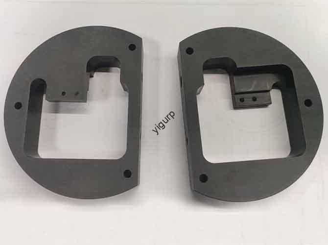
3. How Is the CNC Machining Executed?
This is where the metal (and plastic) meets the tool. Execution happens in three distinct stages to ensure a tolerance of ±0.03mm for critical fits.
Roughing and Semi-Finishing
In the Roughing stage, we remove about 80% of the material. For an AC housing, we mill the outer shape first, then carefully dig the internal cavity. This prevents the plastic from “collapsing” under the pressure of the tool.
In Semi-Finishing, we smooth out the rough edges. This is vital for air ducts. A smooth inner wall reduces air turbulence, which directly lowers the noise level of the final unit.
Final Finishing for Quality
The finishing stage determines how the product looks and feels.
- Housing: We target a surface roughness of Ra ≤0.8μm. This is smooth enough to go straight to the paint booth.
- Heat Sinks: We use specialized cutters to ensure the 0.5–1mm fin spacing is perfectly uniform. If the fins are uneven, the heat exchange will be inefficient.
- Deflectors: These parts control the air direction. We machine the swing shafts with a ±0.02mm tolerance so they move smoothly without “jittering.”
4. What Happens During Post-Processing and Assembly?
After the parts come off the machine, they need a “professional touch” to look like a real consumer product.
Improving Durability and Looks
We start by deburring every edge. For aluminum parts, we often use anodizing to add a layer of protection against moisture. For the indoor unit, we spray matte or glossy PU paint to give it that high-end appliance feel.
Pro Tip: We often add rubber seals to the filter mounting grooves during this stage. This simple step can improve the unit’s air tightness by 20%, ensuring all air passes through the cooling coils rather than leaking around them.
Final Assembly and Debugging
We assemble the core components first—evaporator, condenser, and motor—then add the housing. Once built, we put the prototype through a “boot camp” of tests:
- Airflow Test: We use an anemometer to check if the air speed is uniform.
- Noise Test: Using a sound level meter, we verify the indoor unit stays below 30dB.
- Leakage Test: we fill the drainage port with water to ensure no joints leak into the electronics.
5. How to Tailor the Process for Different Models?
Not all AC prototypes are created equal. Depending on the design, we adjust our focus.
Wall-Mounted Units
The focus here is silence and size. We use thinner aluminum alloys for the housing to keep the unit under 180mm thick. We also spend extra time optimizing the curvature of the air volute to ensure a whisper-quiet operation.
Central AC Outlets
The focus here is durability. Since these are often part of a building’s structure, we use Stainless Steel (304). We utilize 5-axis CNC machining for the deflectors to allow for a wide 0°–120° swing range, ensuring the air reaches every corner of the room.
Discuss Your Projects with Yigu Rapid Prototyping
At Yigu Technology, we view every AC prototype as a “performance validator.” Our team uses 5-axis finishing and CFD simulation to ensure your heat sinks and air ducts meet global energy standards. By integrating 3D scanning to verify dimensions to within ±0.03mm, we help our clients cut rework rates by 25% and get to market 1–2 weeks faster. Whether you need a sleek residential unit or a rugged industrial outlet, we have the expertise to make it happen.
FAQ
How long does the entire CNC machining air conditioning prototype process take?
Usually between 12 and 18 working days. This covers everything from the initial requirements analysis to the final functional debugging and noise testing.
Why is aluminum used for heat sinks instead of just plastic?
Plastic is an insulator. To test if your AC can actually cool a room, you need the high thermal conductivity of aluminum (220 W/m·K) to simulate how heat moves through the system.
Can CNC machining help reduce AC noise?
Yes. By achieving a very smooth surface (Ra ≤0.6μm) on the inner air ducts, we reduce air friction and turbulence, which are the primary causes of “whooshing” sounds in AC units.
What is the standard tolerance for AC prototype assembly?
For critical components like swing shafts and filter grooves, we maintain a tolerance of ±0.02mm to ±0.05mm to ensure a perfect fit and smooth movement.
Would you like me to review your 3D design to identify any potential machining challenges for your AC prototype?