Creating a high-quality CNC machining soymilk machine prototype is a vital step in modern product development. It is far more than a simple visual model; it is a functional tool that validates your design, tests the dynamic balance of blades, and ensures leak-proof performance.
By using CNC machining, you can detect structural flaws before moving to expensive mass production. This guide walks you through the entire journey—from the initial 3D design to the final functional test—to help you build a prototype that is both precise and safe.
What Preparation Ensures a Successful Prototype?
Success starts on the drawing board. If the foundation is weak, the final product will fail during testing. For a soymilk machine, preparation centers on precise 3D modeling and smart material selection to handle heat and food safety.
How to Plan Key 3D Model Details?
You should use professional CAD software like SolidWorks or UG to split the machine into logical modules: the body shell, lid, blade assembly, and base.
- Inner Container: Maintain a tight tolerance of ±0.1mm to ensure the capacity is accurate.
- Blade Mounting Slot: This must be perfectly centered. Even a tiny offset will cause the machine to vibrate or “jitter” at high speeds.
- Sealing Grooves: Design a dedicated path for the silicone sealing ring. If the groove is too shallow, the machine will leak; if it is too deep, the lid won’t close.
Expert Insight: In a recent project, a client missed the tolerance on the blade slot by just 0.15mm. The resulting friction caused the motor to overheat within 30 seconds. Paying attention to these details prevents rework that typically adds 2–3 days to your schedule.
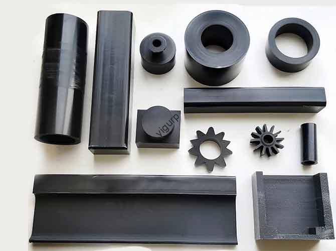
Which Materials Match Each Component Function?
Different parts of the machine face different stresses. You need a mix of transparency, strength, and food safety.
| Component | Recommended Material | Key Advantage | Machinability |
| Inner Container | PC (Polycarbonate) | Heat-resistant, food-grade, transparent | High (requires sharp tools) |
| Body Shell / Handle | ABS Plastic | Low cost, easy to paint, tough | Excellent (fast cutting) |
| Blade Brackets | Aluminum Alloy | High strength, stays cool | Good (needs anodizing) |
| Blades | Stainless Steel 304 | Sharp, rust-proof, food-safe | Moderate (needs slow feed) |
How Does the CNC Machining Process Work?
Once the design is ready, the CNC machining phase turns digital files into physical parts. This stage requires a careful balance of speed and precision.
How to Set Up the Toolpath?
We use CAM software like Mastercam to tell the machine exactly how to move. For a soymilk machine, the tool choice is critical:
- For Blades: We use carbide tools to achieve a razor-sharp edge. This ensures the soybeans are crushed into a fine powder rather than just being “swung” around.
- For Thin Walls: The body shell is often thin. We reserve a 0.2mm deformation allowance. This prevents the plastic from warping as the tool removes material.
What Are the Key Machining Parameters?
Every material has a “sweet spot” for cutting. Using the wrong speed can melt plastic or break tools.
- ABS Plastic: Speed = 1800–2200 rpm. High speeds keep the cut clean.
- Aluminum Alloy: Speed = 1000–1500 rpm. We use liquid coolant here to prevent the metal from sticking to the bit.
- PC Plastic: Speed = 2000–2500 rpm. Fast cutting prevents “stress cracks” in the clear plastic.
Why Is Clamping So Important?
If the material moves even a hair, the part is ruined. We use vacuum adsorption for large plastic shells. This holds the part flat without the “bruising” or crushing marks that mechanical clamps can leave behind.
Can Post-Processing Improve Prototype Performance?
A part straight off the machine often has “tool marks.” Post-processing removes these flaws and gives the prototype a consumer-ready finish.
How to Achieve a Premium Look?
- Sanding and Polishing: We start with 200-grit sandpaper and work up to 800-grit. This makes the ABS shell smooth enough for painting.
- Surface Spraying: We apply food-grade UV paint or rubber oil. This doesn’t just look good; it adds a layer of scratch resistance.
- Anodizing: For aluminum parts, anodizing creates a hard, rust-proof layer. It also allows us to add colors like silver or matte black for a modern aesthetic.
- Silk Screen Printing: We print the “Start,” “Clean,” and capacity scales using high-adhesion ink. This ensures the labels don’t fade after the first few washes.
What Checks Happen Before Assembly?
Before we put it together, we perform a “mini-audit”:
- Caliper Check: Does the inner container hold exactly what the design claims?
- Blade Sharpness: We run a quick manual spin to ensure there is zero jitter.
- Groove Inspection: We verify the sealing ring fits like a glove.
How Do You Validate Prototype Performance?
The final step is the most important: testing. This is where we prove the design works in the real world.
Step-by-Step Assembly Path
- Secure the aluminum motor bracket to the base using M2 screws.
- Drop the blade assembly into the slot. It should spin freely with a gentle flick.
- Press the silicone ring into the lid.
- Snap the button panel into the body shell, ensuring all holes align perfectly.
The Ultimate Testing Checklist
| Test Category | Pass Criteria | Method |
| Functional Test | Blades rotate smoothly with no noise. | Water test / Power-on |
| Sealing Test | Zero leakage from lid or base. | 30-minute run |
| Structural Test | Handle resists 3kg pull force. | Pull gauge |
| Appearance Test | No visible scratches or paint chips. | Visual inspection |
Yigu Technology’s Perspective
At Yigu Technology, we view every soymilk machine prototype as a “design validator.” Our goal is to bridge the gap between an idea and a safe, mass-producible product. We prioritize material safety and dynamic balance.
For all food-contact parts, we strictly use FDA-compliant materials. We also use 3D scanning after machining to check that the tolerance is tighter than <0.05mm. By focusing on these micro-details, we help our clients cut their time-to-market by 1–2 weeks and reduce defects by up to 25%. Whether you need a stunning model for a trade show or a rugged unit for lab testing, we tailor the process to your specific needs.
FAQ: Common Prototype Questions
How long does it take to get a soymilk machine prototype?
The typical lead time is 7–9 working days. This covers the full cycle from CAD optimization to final testing.
Can I use resin for the body shell to save money?
We do not recommend it. Resin is brittle. When the motor spins at high speeds, the vibration can crack a resin shell. ABS plastic is a much safer and more durable choice for functional tests.
What if my prototype leaks during the water test?
Don’t panic. Usually, it’s a sealing ring issue. We check the groove dimensions first (tolerance should be ±0.05mm). If the groove is too deep, adding a thin silicone shim usually fixes the leak in under two hours.
How do you ensure the blades don’t rust?
We use 304 stainless steel and apply a passivation treatment. This removes free iron from the surface, creating a protective layer that keeps the blades safe for food contact.
Is CNC better than 3D printing for this project?
Yes. 3D printing leaves small pores that can trap food particles and bacteria. CNC machining creates solid, smooth surfaces that are hygienic and much stronger for high-speed motor testing.
Discuss Your Projects with Yigu Rapid Prototyping
Are you ready to turn your appliance concept into a reality? At Yigu Technology, we specialize in the precision machining required for modern kitchen electronics. Our team is ready to help you optimize your design for both performance and cost.
Would you like me to review your 3D files and provide a free DFM (Design for Manufacturing) analysis for your soymilk machine project?