In sheet metal manufacturing, getting a perfect, consistent bend is vital. Traditional manual bending often falls short due to human error and slow speeds. The CNC bending machining process solves these problems by using computer-controlled precision. It is the go-to method for everything from automotive brackets to electrical enclosures. This guide breaks down the process step-by-step to help you reduce scrap and deliver high-quality parts every time.
What Is the CNC Bending Machining Process?
The CNC bending machining process is a high-tech way to shape metal. A computer controls a machine called a press brake. This machine uses 3D designs to automate the bending angle, pressure, and tool position. By removing the guesswork, you get parts that are identical and precise.
CNC Bending vs. Manual Bending
Why switch to CNC? The data shows a clear gap in performance between automated and manual methods.
| Aspect | CNC Bending Process | Manual Bending |
| Precision | ±0.1° angle accuracy | ±1° (depends on skill) |
| Speed | 10–15 bends per minute | 2–3 bends per minute |
| Scrap Rate | 2–5% | 10–15% |
| Complexity | Handles 5+ bends easily | Struggles with 3+ bends |
How Does the Process Work Step-by-Step?
A successful bend starts long before the machine moves. Following a linear workflow ensures that every part meets your design specs.
Step 1: Design and Programming
This is the “brain” phase. First, use CAD software to create a 3D model. You must define the material thickness and the bend radius. A tight radius on thick metal can cause cracking, so plan carefully. Next, use CAM software to set the bending sequence. This tells the machine which angle to bend first to avoid hitting the tools.
Step 2: Material Preparation
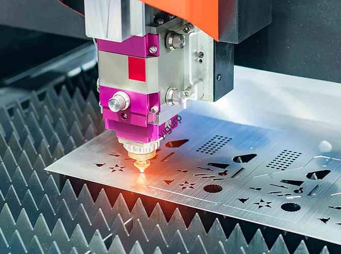
Choose your metal based on the part’s job. Aluminum 6061 is great for lightweight trim, while Stainless Steel 304 resists rust. Once you pick the metal, use a laser cutter to create “blanks.” These are flat sheets that match your part’s unbent size.
Step 3: Machine Setup
Incorrect setup is the main cause of bad parts. You must match the upper punch and lower die to your metal type. For 2mm aluminum, use a 3mm radius die to prevent surface cracks. Set your backgauge—the stop that holds the metal—to the exact starting position.
Step 4: Execution and In-Process Checks
Place the blank on the table. The backgauge will slide it into the perfect spot. When you hit “run,” the press brake lowers the punch with the exact pressure needed. For the first few parts, measure the angle with a protractor. If the angle is off by even 0.5°, adjust the CNC program immediately.
Step 5: Post-Treatment and Inspection
After bending, parts may have sharp edges. Use a deburring tool to smooth them out. Finally, check the surface quality for any dents or cracks. A manufacturer making 1,000 enclosures recently used this flow and cut their production time by 60%.
How to Solve Common Bending Challenges?
Even with the best machines, metal can be stubborn. Here is how to fix the most frequent issues on the shop floor.
- Angle Is Too Small: Metal often “springs back” after a bend. If you want a 90° angle, try programming for 92° to allow for this elastic recovery.
- Material Cracking: This happens if the bend is too sharp. Use a larger die radius or heat the metal slightly before bending.
- Part Misalignment: If parts look crooked, your backgauge might be loose. Recalibrate it with a reference block and tighten all die clamps.
- Machine Vibration: High speeds can cause shaky bends. Reduce the speed to 3–5 mm/s for better stability.
Yigu Technology’s Perspective
At Yigu Technology, we have helped over 250 shops perfect their CNC bending machining process. We find that 70% of delays come from poor setup. Our press brakes use auto-calibration to cut setup time by 40%. We also offer custom die sets for complex, curved bends. For small shops, our training helps operators reduce scrap rates to below 5%. We believe that mastering the setup is the fastest way to boost your productivity.
FAQ
How do I calculate the right press force?
Use this simple formula: Force (kN) = Thickness × Width × Material Factor. For steel, use a factor of 2.5. For aluminum, use 1.5. Most modern CNC panels have a built-in calculator for this.
Can I bend very thin materials?
Yes. For 0.5mm aluminum, use low pressure (20–30 kN) and a narrow V-die. Adding a 2-second hold time in the program helps the thin metal “set” into its new shape.
How often should I maintain the press brake?
Clean the dies daily. Every week, you should lubricate the backgauge rails. Once a month, check for die wear. Good maintenance adds 3 to 5 years to your machine’s life.
Discuss Your Projects with Yigu Rapid Prototyping
Are you ready to improve your sheet metal precision? At Yigu Technology, we provide expert advice on the CNC bending machining process to ensure your parts are flawless. Whether you need automotive components or custom enclosures, we help you pick the right tools and settings.
Would you like a free review of your CAD drawings to optimize your bending sequence?