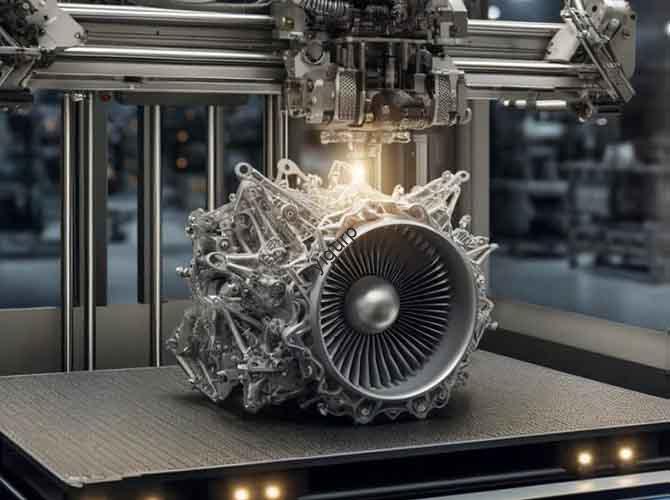
You need a metal part that’s stronger than steel, lighter than titanium, and shaped like something nature dreamed up—with internal channels and lattice structures no tool could ever reach. Traditional manufacturing hits a wall. The solution? Selective Laser Melting (SLM), the pinnacle of metal additive manufacturing (AM). Far more than just “metal 3D printing,” SLM is a sophisticated digital metallurgy process that builds fully dense, high-performance components directly from a CAD file. For engineers and manufacturers, mastering 3D printing SLM technical details is the key to unlocking applications in aerospace, medical, and high-tech industries. This guide demystifies the process, reveals its critical parameters, and shows you how to leverage it for groundbreaking results.
Introduction
In a world demanding lighter, stronger, and more complex metal components, subtractive and formative methods like CNC machining and casting are reaching their limits. Selective Laser Melting (SLM) emerges as a disruptive force. It belongs to the Powder Bed Fusion (PBF) family of AM processes, where a high-power laser selectively fuses fine metal powder particles, layer by layer, to create a solid part. The result is not a porous prototype, but a fully dense, metallurgically sound component with mechanical properties often exceeding cast parts and rivaling forgings. This technology solves the tri-lemma of complexity, weight, and strength, enabling everything from fuel-efficient rocket engines to patient-specific spinal implants. Let’s dive into the technical core of SLM.
What is Selective Laser Melting (SLM)? Core Principles Explained
At its heart, SLM is a digitally controlled, micro-welding process inside a bed of metal powder. Think of it as a highly precise, automated welder building a part from the ground up, one microscopic cross-section at a time.
The Step-by-Step SLM Process Cycle:
- Powder Recoating: A blade or roller spreads a thin, precise layer of metal powder (typically 20-60 microns thick) across the build platform.
- Laser Scanning: A high-power fiber laser (commonly 200W to 1kW) scans the cross-section of the part onto the powder bed. The laser’s energy is absorbed by the powder, raising its temperature past the melting point to create a small, stable melt pool.
- Solidification & Fusion: The melt pool rapidly solidifies, fusing the powder particles together and to the previously solidified layer below. This creates a metallurgical bond.
- Platform Lowering: The build platform lowers by exactly one layer thickness.
- Repetition: The cycle repeats—recoat, scan, fuse—for thousands of layers until the complete part is built, fully encapsulated in unsintered powder.
Key Differentiator from Sintering (SLS): SLM achieves full melting, resulting in >99.5% density. Direct Metal Laser Sintering (DMLS) often implies partial melting/sintering, though in practice, the terms are frequently used interchangeably in industry. SLM is the definitive term for full melt processes.
What Are the Critical Technical Parameters of SLM?
The quality of an SLM part is governed by a complex interplay of laser parameters, material properties, and thermal management. Optimizing these is the essence of 3D printing SLM technical expertise.
The “Laser-Powder Interaction” Trinity:
These three parameters are intrinsically linked and form the core of any process qualification.
| Parameter | Definition & Role | Effect on Part Quality | Optimization Goal |
|---|---|---|---|
| Laser Power (P) | The energy output of the laser source (Watts). Provides the heat input. | Too Low: Insufficient melting, lack-of-fusion porosity, poor mechanical strength. Too High: Excessive evaporation, keyholing porosity, spatter, residual stress. | Find the minimum power to achieve a stable, deep enough melt pool for full density without defects. |
| Scan Speed (v) | The velocity of the laser spot across the powder bed (mm/s). Controls exposure time. | Too Slow: Overheating, balling, part distortion, high residual stress. Too Fast: Incomplete melting, porous structure. | Balance with laser power to achieve a consistent Volumetric Energy Density (VED). |
| Hatch Distance (h) | The spacing between adjacent scan tracks (microns). Determines overlap. | Too Wide: Gaps between tracks, porosity. Too Narrow: Overheating, increased stress, longer build times. | Ensure sufficient overlap (typically 20-50%) for a uniform, dense layer. |
The Master Formula: Volumetric Energy Density (VED)
While not a machine setting, VED is the crucial derived metric that combines the trinity:
VED (J/mm³) = Laser Power (P) / (Scan Speed (v) * Hatch Distance (h) * Layer Thickness (t))
It provides a starting point for parameter development. For common alloys like Ti-6Al-4V or 316L Stainless Steel, VED typically ranges from 50 to 100 J/mm³, but it is only a guide. Optimal parameters are material and machine-specific.
Supporting Parameters That Make or Break a Build:
- Layer Thickness (t): Thinner layers (20-30µm) enable finer features and smoother surfaces but increase build time. Thicker layers (50-60µm) are used for faster, bulkier parts.
- Scan Strategy: The pattern the laser uses (stripes, chessboard, islands) is critical for managing thermal stress and minimizing distortion. Alternating patterns between layers prevents the buildup of stress in one direction.
- Build Chamber Atmosphere: An inert atmosphere (Argon, sometimes Nitrogen) with oxygen levels below 0.1% is mandatory to prevent oxidation of reactive metals like Titanium and Aluminum, which would embrittle the part.
- Preheating: Heating the build platform (up to 200°C for steel, 500°C+ for some superalloys) reduces thermal gradients, mitigating residual stress and cracking in brittle materials.
How Do SLM Parts Compare to Traditional Manufacturing?
SLM isn’t a replacement for all traditional methods; it’s a new tool with a unique profile. The choice depends on the application’s drivers.
| Criteria | Selective Laser Melting (SLM) | CNC Machining (Subtractive) | Investment Casting |
|---|---|---|---|
| Geometric Complexity | Excellent. Free-form, internal channels, lattices, topology-optimized shapes. | Poor. Limited by tool access, undercuts. | Good. Complex external shapes, but internal features limited by core removal. |
| Material Efficiency | Excellent. Near-net-shape, unused powder is ~95% recyclable. | Poor. High waste (buy-to-fly ratio can be 10:1 for aerospace parts). | Moderate. Requires gates and runners; some material loss. |
| Lead Time for Prototypes | Excellent. Direct from CAD in days. | Good to Moderate. Requires programming and fixturing. | Poor. Requires pattern and mold making (weeks). |
| Mechanical Properties | Excellent to Good. High strength, often anisotropic. Can match wrought properties with proper heat treatment. | Excellent. Properties of wrought stock material. | Good. Properties of cast material; can have porosity. |
| Surface Finish | Moderate (as-built). Ra 10-25 µm, typical “wavy” appearance. Requires post-processing for smoothness. | Excellent. Can achieve mirror finishes. | Moderate to Good. Depends on mold surface. |
| Economic Batch Size | Small to Medium (1 – 10,000 units). High fixed cost (machine), low variable cost per part. | All sizes. Economical for prototypes to high volume. | Medium to High (100+ units). High pattern cost amortized over volume. |
Case Study: Aerospace Bracket – A Quantitative Win
- Challenge: Design a secondary aircraft bracket that must withstand specific loads with minimal weight.
- Traditional Design (Machining): A solid block of titanium is machined, resulting in a 450-gram bracket.
- SLM + Topology Optimization: Software generates an organic, lattice-filled shape that uses material only where needed. The SLM-produced bracket weighs 280 grams (38% lighter) and is printed as a single, consolidated part that would require multi-piece assembly if machined. It meets all strength requirements, reduces aircraft fuel burn, and is produced on-demand, eliminating inventory.
What Are the Key Applications and Materials for SLM?
SLM excels where its unique capabilities solve critical problems.
Dominant Industries and Use Cases:
- Aerospace & Defense:
- Parts: Fuel nozzles, turbine blades, structural brackets, satellite components.
- Driver: Weight reduction (lightweighting), part consolidation, and performance of high-temperature superalloys (Inconel).
- Example: GE’s LEAP fuel nozzle is a famous consolidation of 20 parts into one SLM-printed Inconel piece, improving efficiency and durability.
- Medical & Dental:
- Parts: Orthopedic implants (hips, knees, spinal cages), surgical guides, dental crowns/copings.
- Driver: Patient-specific customization from CT scan data and the ability to create porous surface structures that promote osseointegration (bone ingrowth).
- Material: Biocompatible Ti-6Al-4V ELI is the gold standard.
- Automotive & Motorsport:
- Parts: Lightweight structural components, custom cooling channels for engines/molds, hydraulic manifolds.
- Driver: Rapid prototyping of functional metal parts, low-volume production for racing, and performance optimization.
Common SLM Materials and Their Properties:
| Material | Key Characteristics | Typical Applications |
|---|---|---|
| Ti-6Al-4V (Grade 5/23) | High strength-to-weight ratio, excellent biocompatibility, good corrosion resistance. | Aerospace structures, medical implants. |
| 316L Stainless Steel | Excellent corrosion resistance, good ductility and toughness. | Chemical processing parts, marine, food-safe applications. |
| AlSi10Mg (Aluminum) | Lightweight, good thermal properties, decent strength. | Heat exchangers, lightweight housings, automotive parts. |
| Inconel 718 (Nickel Superalloy) | Exceptional high-temperature strength and oxidation resistance. | Turbine blades, rocket engine components, high-heat fixtures. |
| Copper Alloys (e.g., CuCrZr) | Excellent thermal and electrical conductivity. | Induction coils, heat sinks, electrical connectors. |
What Are the Challenges and Post-Processing Requirements?
SLM is not a push-button solution. Awareness of its demands is key to success.
Inherent Challenges:
- High Residual Stress: The rapid heating and cooling cycles induce significant stress, which can cause warping, cracking, or delamination during the build. This is managed via support structures, scan strategies, and preheating.
- Support Structures: Necessary to anchor parts to the build plate and to support overhangs (typically >45°). They are metal and must be mechanically removed, adding cost and time.
- Powder Management: Metal powder is expensive, reactive, and a potential health hazard (inhalation). Handling requires closed-loop systems, inert gas circulation, and strict safety protocols.
The Essential Post-Processing Chain:
An SLM part is not finished when the build job ends. A typical workflow includes:
- Stress Relief Heat Treatment: Performed before part removal from the plate to prevent distortion.
- Wire EDM Removal: Parts are cut from the build plate using Electrical Discharge Machining.
- Support Removal: Via machining, grinding, or wire EDM.
- Hot Isostatic Pressing (HIP): For critical, high-integrity parts (aerospace, medical). HIP uses high heat and pressure to eliminate internal porosity and heal defects.
- CNC Machining: To achieve tight tolerances on critical interfaces (e.g., threads, sealing surfaces) and improve surface finish.
- Surface Finishing: Sandblasting, polishing, or tumbling to achieve the desired aesthetic and surface roughness.
The Future of SLM: Trends and Advancements
The technology is rapidly evolving:
- Multi-Laser Systems: Modern machines use 2, 4, or even more lasers scanning simultaneously, dramatically increasing build speed for large parts.
- Process Monitoring & AI: Integrated melt pool monitoring, layer-wise imaging, and AI-driven anomaly detection enable closed-loop control and quality assurance, moving towards certified “first-time-right” production.
- New Material Development: Alloys specifically designed for the unique thermal cycles of SLM are emerging, offering properties unattainable with conventional processing.
Conclusion
Selective Laser Melting is far more than a novel way to make metal parts. It is a fundamentally new manufacturing paradigm that decouples geometric complexity from cost and enables the creation of high-performance, lightweight structures directly from digital designs. Mastering the 3D printing SLM technical landscape—from parameter optimization and material science to design-for-AM and post-processing—is essential for engineers and companies aiming to lead in innovation. While challenges around cost, speed, and skill remain, the trajectory is clear: SLM is moving from a prototyping tool to a cornerstone of next-generation, digital manufacturing for the most demanding applications on earth and beyond.
FAQ: Your Selective Laser Melting Questions Answered
Q: What is the fundamental difference between SLM and DMLS?
A: Historically, DMLS (Direct Metal Laser Sintering) was a trademark of EOS GmbH and implied a process that sintered powder without full melting. SLM explicitly denotes full melting. In modern industrial practice, especially with machines from vendors like SLM Solutions, the term SLM is used for full-melt processes. However, marketing has blurred the lines, and “Laser Powder Bed Fusion (LPBF)” is now the preferred, vendor-neutral term encompassing both. For all intents and purposes, when discussing fully dense metal parts, they refer to the same family of technology.
Q: How strong are SLM parts compared to forged metal?
A: In terms of ultimate tensile strength and yield strength, properly processed and heat-treated SLM parts can meet or exceed the properties of cast parts and approach those of wrought/forged materials. However, fatigue strength and ductility can be lower in the as-built state due to residual stress, surface roughness, and potential micro-defects. Post-processing like HIP (Hot Isostatic Pressing) and surface machining are often used to bring fatigue performance in line with forged standards, particularly for aerospace components.
Q: What is the smallest feature size or thinnest wall possible with SLM?
A: This depends on the material, laser spot size, and powder size. As a practical guideline, minimum unsupported wall thicknesses are typically around 0.4-0.5 mm. Fine features like pins or sharp corners can be challenging below 0.3 mm due to heat accumulation and lack of support from surrounding powder. High-resolution machines with smaller spot sizes (e.g., 30 µm) can push these limits further.
Q: Why are SLM parts so expensive?
A: Cost drivers are multifaceted: High capital investment for the machine and ancillary equipment (powder handling, sieving, etc.). Expensive raw materials (gas-atomized, spherical powder). Lengthy build times (even with multi-lasers). Significant post-processing labor (support removal, heat treatment, machining). Skilled operator/engineer time for file preparation and parameter management. The value proposition lies in part performance, consolidation, and weight savings, not per-kilogram cost compared to billet.
Q: Can SLM be used for serial production, or is it only for prototyping?
A: Absolutely for serial production. It is increasingly used for low-to-medium volume serial production (tens to thousands of units) in industries like aerospace (e.g., satellite components, turbine blades) and medical (custom implants). Its economic viability improves with part complexity and the value of weight savings or performance gains. For very high volumes (millions), traditional methods are still more economical.
Discuss Your Projects with Yigu Rapid Prototyping
Pushing the boundaries of what’s possible with metal requires a partner who understands both the promise and the intricacies of SLM technology. Are you exploring a topology-optimized component, a complex internal cooling geometry, or a low-volume production run of a high-value metal part? At Yigu Rapid Prototyping, we operate a fleet of advanced multi-laser SLM systems and offer deep expertise in material selection, design for additive manufacturing (DfAM), process parameter optimization, and the full post-processing chain. Our engineering team can guide you from initial concept through to a validated, flight-ready component. Contact us to discuss how SLM can transform your next metal part from a constraint into a competitive advantage.