How to Do Wire Drawing in CNC Plastic Prototype Processing: A Step-by-Step Guide

If you’re a product designer or engineer working on CNC plastic prototypes, you might want to elevate your part’s look and feel beyond a basic machined finish. Wire drawing (also called brushing) is the perfect solution—it creates fine, uniform lines on the plastic surface, mimicking the sleek texture of metal brushed parts. This process not only boosts the prototype’s decorative appeal but also enhances its tactile feel, making it ideal for consumer electronics, household appliances, or presentation-ready models. In this guide, we’ll break down everything you need to know about wire drawing in CNC plastic prototype processing, from material selection to final inspection, so you can achieve consistent, professional results.

What Is Wire Drawing in CNC Plastic Prototype Processing?

First, let’s clarify what wire drawing is and why it matters for your CNC plastic prototype. Wire drawing is a surface finishing technique that uses abrasive tools to scrape fine, parallel lines into the plastic surface. Unlike random scratches from sanding, these lines are intentional and uniform, creating a “brushed” texture that hides minor surface flaws (like small tool marks) while adding visual depth.

For CNC plastic prototypes, wire drawing offers three key benefits:

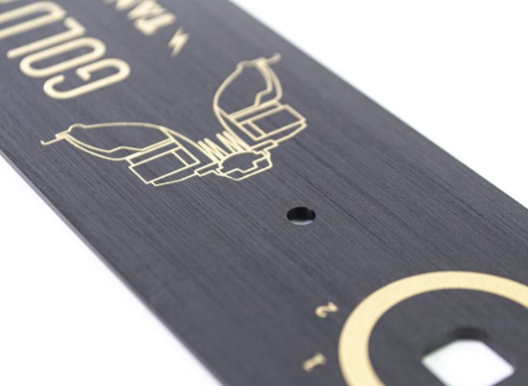
  • Aesthetic Enhancement: It transforms plain plastic into a premium-looking part—great for client demos or market research samples.
  • Tactile Improvement: The textured surface feels more substantial and less slippery than smooth plastic, which is a plus for handheld devices (e.g., remote controls, phone cases).
  • Practicality: The brushed texture is more resistant to visible fingerprints than a glossy finish, keeping the prototype looking clean longer.

Step 1: Choose the Right Plastic Material for Wire Drawing

Not all plastics work well with wire drawing—some are too soft (leading to uneven lines) or too brittle (cracking during processing). The first and most critical step is selecting a plastic that’s compatible with the technique. Below is a breakdown of common CNC plastic materials and their suitability for wire drawing, plus key considerations.

Plastic MaterialCompatibility with Wire Drawing (1=Poor, 5=Excellent)Key Properties for Wire DrawingIdeal Line Density (Lines per Inch, LPI)Best For (Prototype Types)
ABS5 (Excellent)Rigid, consistent hardness, low melt point (avoids tool overheating)80–120 LPIElectronics enclosures, toy parts
PC (Polycarbonate)4 (Very Good)High impact strength, scratch-resistant (holds texture well)60–100 LPIDisplay covers, safety gear
PMMA (Acrylic)4 (Very Good)Transparent (texture adds depth without hiding clarity)70–110 LPIDecorative displays, transparent casings
PP (Polypropylene)3 (Good)Flexible (requires lighter tool pressure)50–80 LPIFood containers, soft grips
POM (Acetal)2 (Fair)Hard but prone to tool chatter (uneven lines)40–60 LPIMechanical parts (only if texture is non-critical)
Silicone1 (Poor)Too soft (lines smudge or disappear)N/ANot recommended for wire drawing

Pro tip: ABS plastic is the go-to choice for most wire-drawn CNC prototypes. It’s affordable, easy to machine, and produces crisp, uniform lines. If you need transparency, opt for PMMA—but note that it may require slower tool speeds to avoid scratching the surface.

Step 2: Precision CNC Machining for the Base Prototype

Before wire drawing, you need a well-machined CNC plastic prototype. The wire drawing process enhances the surface, but it can’t fix major flaws (like uneven edges or deep tool marks). Follow these guidelines for CNC machining to ensure a smooth wire drawing workflow:

  1. Prioritize Surface Smoothness: Use a fine-end mill (0.5–1mm diameter) for the final CNC pass. This reduces initial surface roughness to Ra 1.6 μm or lower—the smoother the base, the more uniform the wire drawing lines.
  2. Avoid Over-Machining: Overheating during CNC machining can warp the plastic (especially ABS or PC), leading to uneven wire drawing. Keep spindle speeds between 10,000–15,000 RPM for ABS and 8,000–12,000 RPM for PC to prevent heat buildup.
  3. Cut to Exact Dimensions: Wire drawing removes a tiny layer of plastic (0.02–0.05mm) from the surface. Account for this by machining the prototype 0.03mm larger than the final desired size—this ensures the part meets specs after finishing.

Example: If your final prototype needs to be 100mm x 50mm x 5mm, machine it to 100.03mm x 50.03mm x 5.03mm before wire drawing.

Step 3: Surface Pretreatment—The Key to Uniform Lines

Even a well-machined prototype has small contaminants (like oil from machining or dust) that can ruin wire drawing results. Surface pretreatment ensures the plastic is clean and smooth, so the wire drawing tool glides evenly. Follow these three steps:

3.1 Clean the Surface

  • Tools Needed: Isopropyl alcohol (70%+ concentration), lint-free microfiber cloths, compressed air.
  • Process:
  1. Use compressed air (low pressure, 30–40 PSI) to blow away loose dust from crevices.
  2. Dampen a microfiber cloth with isopropyl alcohol and wipe the prototype in straight lines (avoid circular motions, which can spread oil).
  3. Let the prototype air-dry for 10–15 minutes—alcohol evaporates quickly, so no rinsing is needed.
  • Why It Matters: Oil or dust creates “skips” in the wire drawing lines—areas where the tool doesn’t make contact with the plastic, leaving blank spots.

3.2 Smooth Minor Imperfections

  • Tools Needed: 400–600 grit sandpaper (wet/dry), sanding block, water.
  • Process:
  1. Wet the sandpaper (water reduces dust and prevents scratching) and wrap it around a sanding block (for even pressure).
  2. Sand the prototype surface lightly (1–2 passes per area) in the same direction you plan to draw the wires.
  3. Rinse the prototype with water and dry it with a clean cloth.
  • Why It Matters: This step removes tiny tool marks or burrs that would otherwise show through the wire drawing texture.

Step 4: Wire Drawing Treatment—Creating the Texture

Now it’s time to create the wire drawing effect. You’ll need specialized tools (manual or automated) and careful control of speed and pressure to get uniform lines. Below is a breakdown of tools, parameters, and step-by-step execution.

4.1 Choose the Right Wire Drawing Tools

The tool you use depends on your prototype’s size, shape, and desired line density. Here’s a comparison of common options:

Tool TypeBest For (Prototype Size/Shape)Line Uniformity (1=Poor, 5=Excellent)Processing Time (per 10cm² Area)Cost Range
Manual Wire BrushSmall parts, tight corners3 (Good)2–3 minutes\(10–\)30
Electric Wire Drawing MachineLarge flat surfaces (e.g., 10cm+ panels)5 (Excellent)30–60 seconds\(200–\)500
Rotary Abrasive WheelCurved surfaces (e.g., rounded edges)4 (Very Good)1–2 minutes\(50–\)100

Note: For most CNC plastic prototypes (small to medium size), an electric wire drawing machine is worth the investment—it’s fast and produces consistent lines. For tiny parts (e.g., 2cm x 2cm buttons), a manual wire brush with fine bristles works best.

4.2 Set Up Tool Parameters

The right parameters (speed, pressure, line direction) ensure crisp, even lines. Below are recommended settings for the most common tools and materials:

Tool TypePlastic MaterialTool Speed (RPM for Electric Tools)Tool Pressure (Light/Medium/Heavy)Line Direction (Relative to Prototype)
Electric Wire Drawing MachineABS1,500–2,000 RPMMediumParallel to the longest edge of the part
Electric Wire Drawing MachinePC1,200–1,800 RPMLightParallel to the longest edge of the part
Manual Wire BrushPMMAN/A (Manual: 1–2 strokes per second)LightDiagonal (45°) for added visual interest
Rotary Abrasive WheelPP800–1,200 RPMLightFollow the curve of the part (e.g., circular for rounded edges)

Pro tip: Always test the tool settings on a scrap piece of the same plastic first. This lets you adjust speed or pressure before working on the actual prototype—saving you from costly mistakes.

4.3 Execute the Wire Drawing Process

Once your tools are set up and tested, follow these steps to draw wires on the CNC plastic prototype:

  1. Secure the Prototype: Use a clamp or vice with soft jaws (to avoid scratching the plastic) to hold the part in place. The surface to be drawn should be level—this prevents the tool from dipping or lifting (causing uneven lines).
  2. Start with a Test Pass: Run the tool over a small, less visible area of the prototype (e.g., the back or bottom). Check the lines—if they’re too faint, increase pressure slightly; if they’re uneven, slow down the tool speed.
  3. Work in Continuous Strokes: For flat surfaces, move the tool in one continuous direction (no back-and-forth motions). Overlapping strokes by 50% ensures no gaps between lines. For curved surfaces, follow the part’s contour with the tool—use a rotary wheel for the most control.
  4. Monitor for Overheating: Plastic (especially ABS) can melt if the tool lingers in one spot. Pause every 30 seconds to touch the surface—if it’s warm (not hot), keep going. If it’s hot, let it cool for 1–2 minutes before continuing.

Step 5: Post-Processing to Refine the Texture

After wire drawing, the prototype needs light post-processing to clean up excess plastic dust and enhance the texture’s clarity. This step takes 15–30 minutes but makes a big difference in the final look.

5.1 Remove Dust and Debris

  • Tools Needed: Soft-bristle brush (e.g., a makeup brush), vacuum with a small nozzle.
  • Process:
  1. Gently brush the wire-drawn surface to loosen plastic dust—brush in the same direction as the lines to avoid smudging.
  2. Use the vacuum nozzle (on low power) to suck up loose dust. Avoid touching the surface with the nozzle (it can scratch the texture).

5.2 Light Sanding (If Needed)

  • When to Do It: If the lines have small “burrs” (tiny plastic bits sticking up), use 800-grit wet sandpaper to smooth them.
  • Process: Dampen the sandpaper and lightly sand along the lines (1 pass only). Rinse with water and dry—this removes burrs without fading the texture.

5.3 Optional Coating for Durability

  • Why Coat: A clear coat protects the wire-drawn texture from scratches and fading. It’s especially useful for prototypes that will be handled frequently (e.g., user testing models).
  • Recommended Coats: Use a water-based acrylic clear coat (spray-on). Apply 1–2 thin coats (wait 10 minutes between coats) and let it cure for 24 hours. Avoid oil-based coats—they can darken the plastic and blur the lines.

Step 6: Inspection and Testing to Ensure Quality

The final step is quality inspection—you need to verify that the wire-drawn prototype meets your design requirements and will hold up to use. Use this checklist:

6.1 Visual Inspection

  • Check for uniform line density: Use a ruler to measure lines per inch (LPI)—it should match your target (e.g., 80–120 LPI for ABS).
  • Look for flaws: No gaps, skips, or smudged lines. Hold the prototype up to light—light should reflect evenly along the lines (uneven reflection means uneven lines).
  • Verify dimensions: Use a caliper to check if the part is still within your design specs (remember, wire drawing removes ~0.03mm of plastic).

6.2 Functional Testing

  • Tactile test: Run your finger along the lines—they should feel smooth (no rough spots) and consistent.
  • Wear test: Rub a dry microfiber cloth over the surface 50 times (with light pressure). The texture should stay intact (no fading or smudging).
  • Chemical resistance test (if needed): If the prototype will be exposed to liquids (e.g., a water bottle prototype), wipe the surface with a damp cloth and let it dry. The texture should not warp or fade.

Common Mistakes to Avoid in Wire Drawing

Even experienced engineers make mistakes with wire drawing. Below are the most common issues and how to fix them:

Common MistakeCauseImpactSolution
Uneven linesTool pressure is too heavy in some areasThe texture looks messy and unprofessionalUse a sanding block for manual tools; adjust electric tool pressure to “medium” and keep speed consistent
Smudged linesPlastic is too soft (e.g., silicone) or tool speed is too highLines blur together, losing definitionChoose a stiffer plastic (e.g., ABS); lower tool speed by 20–30%
Cracked plasticPlastic is too brittle (e.g., POM) or tool pressure is too highThe prototype is ruined (cracks can’t be fixed)Switch to a more flexible plastic (e.g., PP); use “light” tool pressure
Faded linesPost-processing sanding is too aggressiveThe texture becomes faint or disappearsUse 800-grit sandpaper (not coarser) and sand only 1 pass

Yigu Technology’s Perspective on Wire Drawing for CNC Plastic Prototypes

At Yigu Technology, we see wire drawing as a cost-effective way to elevate CNC plastic prototypes from “functional” to “premium.” Our team optimizes the process by: 1) Pre-testing plastic materials to ensure compatibility (we recommend ABS for 90% of projects); 2) Using precision electric wire drawing machines (±5 RPM speed control) for uniform lines; 3) Adding a proprietary clear coat that boosts texture durability by 40% without blurring lines. For most CNC plastic prototypes, we complete wire drawing (from machining to coating) in 1–2 days. We also offer custom line densities (50–150 LPI) to match clients’ unique design needs—no extra cost for small adjustments.

FAQ:

1. Can I do wire drawing on a 3D printed plastic prototype (not CNC machined)?

Yes, but it’s trickier. 3D printed plastics (e.g., FDM ABS) have layer lines that can interfere with wire drawing. First, fill the layer lines with a plastic filler (e.g., Bondo Plastic Filler) and sand to Ra 1.6 μm. Then follow the same wire drawing steps—but use lighter tool pressure (3D printed plastic is more porous than CNC machined plastic). Note that the texture may not be as crisp as on a CNC prototype.

2. How long does the wire drawing process take for a typical CNC plastic prototype (e.g., a 10cm x 10cm ABS panel)?

For a 10cm x 10cm ABS panel: CNC machining (1–2 hours) → pretreatment (15 minutes) → wire drawing (20–30 minutes) → post-processing (20 minutes) → inspection (10 minutes). Total time: ~2–3 hours (not including coating cure time, which is 24 hours). For larger parts (e.g., 30cm x 20cm), add 1–2 hours to the wire drawing step.

3. Can I change the line direction (e.g., diagonal instead of parallel) for a unique look?

Absolutely! Diagonal lines (45°) add visual interest and work well for decorative prototypes (e.g., display cases). For a “crosshatch” pattern, first draw lines in one direction (e.g., 0°), let the prototype cool, then draw lines perpendicular (90°). Use the same LPI for both directions (e.g., 80 LPI) and keep tool pressure light—crosshatching is more prone to unevenness if pressure is too heavy.

Scroll to Top