Introduction
You need metal prototypes—brackets, enclosures, connectors, gears—to test your design before mass production. CNC machining works for some parts. 3D printing works for others. But when you need thin, strong, formed metal parts that replicate stamped production parts, nothing beats prototype metal stamping.
This process shapes metal sheets (0.5mm–3mm thick) into functional prototypes using dies and presses. Unlike mass production stamping (which uses expensive, high-volume tooling), prototype stamping prioritizes flexibility, cost efficiency, and rapid validation.
This guide covers everything: core goals, step-by-step workflow, die selection, quality control, and key precautions to help your team avoid common pitfalls.
What Are the Core Goals of Prototype Metal Stamping?
Before starting, clarify your objectives. They guide every decision—from material selection to die design.
| Goal | Description | Real-World Example |
|---|---|---|
| Design Validation | Verify if the prototype’s structure (holes, bends, shapes) matches 2D/3D drawings and functional needs | Testing if a stainless steel electronic device shell (with 4 mounting holes) fits with internal circuit boards |
| Mass Production Feasibility | Identify potential issues (material tearing, dimensional) that could arise in large-scale stamping | Simulating how an aluminum automotive bracket bends—ensuring no cracks in mass production |
| Assembly Compatibility | Confirm the prototype fits with other components (plastics, electronics, screws) | Checking if a stamped copper connector (with M3 threads) securely fastens to a plastic sensor housing |
| Cost and Cycle Time Estimation | Gather data (die costs, processing time) to forecast mass production budgets | Using a prototype die’s $500 cost to estimate that production dies will cost $10,000 and run 100 parts/hour |
What Is the Step-by-Step Prototype Metal Stamping Workflow?
The process follows a linear, repeatable sequence. Each stage builds on the previous one to ensure precision and consistency.
Step 1: Preliminary Preparation (Lay the Foundation)
This stage defines requirements and creates design documents to avoid rework.
Requirements Analysis
- Clarify prototype purpose: Visual verification, structural testing, or assembly matching?
- Define material specs: Thickness (0.5mm–3mm), hardness, ductility (≥10% elongation for bending), corrosion resistance
- Confirm quantity: 1–50 units (standard for prototype stamping)
Design and Drawing Creation
Provide 2D CAD drawings or 3D STP/IGES models with:
- Critical dimensions (e.g., hole diameter: 5mm ±0.1mm) and tolerances (±0.1mm for most prototype parts)
- Bending parameters: Bending radius ≥1x material thickness (to avoid cracking) and angle tolerance ±1°
- Special notes: Surface treatment, burr control ≤0.05mm, or emulsion protection to prevent rust during processing
Step 2: Die Design and Production (Choose the Right Tool)
Prototype dies prioritize cost and speed over high-volume durability. Select based on part complexity and batch size.
| Die Type | Best For | Cost Range | Lead Time | Key Advantages |
|---|---|---|---|---|
| Simple Soft Dies (zinc alloy, resin) | Basic parts (flat blanks, simple bends) | $300–$1,000 | 2–5 days | Low cost, fast; ideal for 1–10 units |
| Multi-Process Soft Dies (combined blanking + bending) | Parts with 2–3 processes (e.g., clip with 2 bends and 1 hole) | $800–$2,000 | 5–7 days | Handles moderate complexity without expensive hard tooling |
| Semi-Hard Dies (low-carbon steel) | Complex parts (deep stretches, multiple holes) | $2,000–$5,000 | 7–10 days | More durable; suitable for 30–50 units |
Critical Die Debugging Steps
Gap adjustment: Set die clearance to 5%–10% of material thickness (e.g., 0.05mm–0.1mm for 1mm aluminum). This ensures clean cuts and prevents burrs.
Force and stroke testing: Use a press to test punching force (e.g., 5–10 tons for 1mm stainless steel). Avoid overloading—it causes material tearing or die damage.
Sample trial: Stamp 1–2 test parts to check dimensional accuracy. Adjust die position or clearance if deviations exceed ±0.1mm.
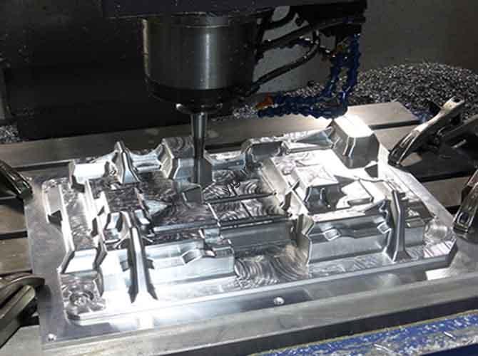
Step 3: Stamping Processing (Shape the Metal)
Follow these sub-steps to transform metal sheets into prototypes, with strict quality checks at each stage.
Material Cutting
Cut metal sheets (e.g., 6061 aluminum, 304 stainless steel) to size using laser cutting or shearing. Reserve 1mm–2mm processing allowance for subsequent steps.
Example: For a 50mm×30mm prototype, cut the sheet to 52mm×32mm.
Core Stamping Operations
Choose operations based on part design. Most prototypes use 1–3 of these:
| Operation | Purpose | Key Parameters | Example |
|---|---|---|---|
| Blanking | Cut sheet into basic part shape | Die clearance: 5–10% of thickness; Press speed: 10–20 strokes/min | Cutting stainless steel into 50mm×30mm rectangle |
| Bending | Shape blank into angles | Bending radius: ≥1x thickness; Angle tolerance: ±1°; Pressure: 3–8 tons for 1mm aluminum | Bending aluminum blank into 90° bracket |
| Stretching | Form deep cavities or curved surfaces | Stretch ratio: ≤2.5; Press speed: 5–15 strokes/min; Use lubricant (emulsion) | Stretching copper sheet into 10mm deep cup |
| Turning/Tapping | Add threads (M1.6–M6) for assembly | Thread depth: 1.5x thread diameter; Tap speed: 50–100 RPM | Tapping M3 thread into brass connector |
In-Process Quality Control
Check for defects:
- Burrs: ≤0.05mm
- Scratches: No visible marks under 10x magnification
- Deformation: Flatness ≤0.1mm per 100mm
Use tools: Caliper (for dimensions), plug gauges (for holes), projectors (for complex shapes) to ensure tolerances within ±0.1mm.
Step 4: Post-Treatment (Enhance Function and Aesthetics)
Post-treatment improves durability, appearance, and compatibility.
| Process | Purpose | Application Example |
|---|---|---|
| Deburring and Cleaning | Remove sharp edges and contaminants | Polishing burrs with wire brush; ultrasonic cleaning (40–60°C, 10–15 min) to remove oil and metal dust |
| Surface Treatment | Improve corrosion resistance and appearance | Plating: Nickel (rust prevention), chrome (mirror finish), zinc (low-cost corrosion); Spraying: Powder coating (color); Anodizing: For aluminum parts; Silk screen: Printing logos or part numbers |
| Heat Treatment (optional) | Strengthen parts for high-stress applications | Quenching + tempering for carbon steel (HRC 30–40); Annealing for aluminum to reduce brittleness after bending |
Step 5: Assembly and Testing (Validate Functionality)
Turn stamped parts into usable prototypes and verify performance.
Component Assembly
Fasten stamped parts with other components using:
- Screws: M1.6–M6, matching tapped holes
- Snap fits: For plastic-metal combinations
- Welding: Laser welding for thin stainless steel; argon arc welding for thick aluminum
Functional Testing
Simulate real-world use:
- Structural strength: Apply load (e.g., 5kg for a drone bracket) and check deformation (≤0.2mm)
- Pressure resistance: Test sealed parts for leaks under 50kPa pressure
- Environmental simulation: Expose prototypes to -20°C to 60°C temperature cycles or 95% humidity
Step 6: Delivery and Iteration (Refine Based on Feedback)
Quality Documentation: Provide test reports with:
- Dimensional records (e.g., hole diameter: 5mm ±0.05mm)
- Surface quality photos (no scratches or plating defects)
- Functional test results (e.g., “Passed 1000 vibration cycles without damage”)
3D Scanning: For complex parts, generate STL files via 3D scanning to let customers compare prototypes with original 3D models.
Optimization: Adjust dies or processes based on feedback. Example: Modify bending radius from 1mm to 1.5mm to reduce cracking, or increase die clearance to eliminate burrs.
What Key Precautions Prevent Failures?
Prototype metal stamping is prone to issues like material cracking, dimensional, and high costs. Here are critical safeguards.
Material Selection
Avoid extremes:
- Too soft (pure aluminum, 1100 series): Causes excessive deformation, leading to out-of-tolerance parts
- Too hard (high-carbon steel): Wears dies quickly (reducing die life by 50% ) and requires higher press force
Prioritize corrosion resistance: For outdoor or wet environments (marine sensors), choose 304 stainless steel or galvanized sheets—they avoid rust during testing and storage.
Cost Control
Simplify design: Reduce the number of stamping steps (merge 2 bends into 1 if possible) or eliminate non-critical features (decorative grooves) to lower die complexity and cost.
Use soft dies for small batches: For 1–10 units, soft dies cost 70% less than semi-hard dies. Only upgrade if you need 30+ units.
Reuse dies: Design dies to be adjustable (interchangeable punch heads) so they can be modified for similar prototype parts—saves $500–$1,500 per new project.
Timeline Management
Plan ahead: The full process takes 5–15 days:
- Die production: 2–10 days
- Stamping + post-treatment: 3–5 days
Add 2–3 buffer days for iterations (die adjustments, re-testing).
Communicate clear deadlines: Share design finalization dates with your die supplier. Delays in drawing approval can extend lead time by 3–5 days.
What Are Typical Application Scenarios?
The prototype metal stamping process solves unique problems across industries.
| Industry | Application Example | Key Benefits |
|---|---|---|
| Electronics | Stamping aluminum alloy shells for wireless routers (with 4 mounting holes and 2 bends) | Validates fit with circuit boards and heat dissipation; avoids costly mold rework for mass production |
| Automotive | Creating stainless steel brackets for car door locks (with 1 bend and M4 threads) | Tests assembly compatibility with plastic components; verifies structural strength under vibration |
| Mechanical Engineering | Stamping carbon steel gears (simple tooth profiles) for conveyor systems | Checks gear meshing; estimates wear resistance for mass production |
| Medical Devices | Producing titanium alloy clips (0.5mm thick, thin-walled) for surgical tools | Ensures biocompatibility (via post-treatment) and precise dimensions (±0.05mm) for safe surgery use |
Conclusion: Prototype Stamping Is Risk Reduction, Not Extra Cost
Prototype metal stamping isn’t about making parts—it’s about validating designs before committing to expensive production tooling.
When you skip prototypes and jump straight to mass production, you risk:
- Aluminum shells that bend under load
- Stainless steel brackets with misaligned holes
- $10,000–$50,000 in mold rework costs
The prototype process catches these issues early, when fixes are cheap and fast.
By following the steps in this guide—clear goals, right die selection, proper parameter optimization, thorough testing—you transform prototype stamping from an optional step into a strategic advantage.
Invest in prototype stamping not as an extra cost, but as a way to get mass production right the first time.
FAQ: Prototype Metal Stamping
Can prototype metal stamping handle parts thicker than 3mm?
Not recommended. Parts thicker than 3mm require higher press force (20+ tons) and harder dies (increasing cost by 200%+ ), undermining prototype cost-efficiency. For thick parts, use CNC machining instead.
How accurate are prototype metal stamping parts?
Standard accuracy is ±0.1mm for most dimensions (holes, bends, lengths). For critical features (e.g., M1.6 threads), accuracy can improve to ±0.05mm with semi-hard dies and strict die debugging.
Is prototype metal stamping cheaper than 3D printing for metal parts?
It depends on quantity:
- 1–5 units: Metal 3D printing (SLM) is cheaper ($100–$300 per part)
- 10–50 units: Prototype stamping becomes more cost-effective—soft dies ($300–$1,000) plus $5–$20 per part beats 3D printing’s $100+ per part
What materials work best for prototype stamping?
Most common: 6061 aluminum, 304 stainless steel, brass, copper, and low-carbon steel. Avoid extremely hard materials (high-carbon steel) or very soft ones (pure aluminum) unless absolutely necessary.
How do I prevent burrs on stamped prototypes?
Proper die clearance is key—set to 5–10% of material thickness. If burrs persist, add a deburring step (wire brushing, electrolytic deburring) to the post-treatment process.
Can I stamp threads into prototype parts?
Yes—use tapping as a secondary operation after stamping. For M1.6–M6 threads, ensure hole diameter matches standard tap drill sizes. Thread depth should be 1.5x thread diameter.
What’s the fastest way to get prototype stamped parts?
Use simple soft dies (zinc alloy or resin) for basic geometries. These take 2–5 days to produce versus 7–10 days for semi-hard dies. Communicate clearly with your supplier and approve drawings quickly.
Discuss Your Projects with Yigu Rapid Prototyping
At Yigu Technology, we see the prototype metal stamping process as a critical “risk reducer” for product teams. Too many clients skip prototypes and jump to mass production—only to discover their aluminum shell bends or their bracket holes misalign, costing $10,000–$50,000 in mold reworks.
Our approach: We help clients select the right die type (soft dies for small batches, semi-hard for complex parts) and optimize stamping parameters (bending radius, die clearance) to cut iteration time by 30% .
Example: We helped an electronics client fix a burr issue in their router shell prototype by adjusting die clearance from 0.08mm to 0.1mm—saving 5 days of rework.
Got a metal prototype project? Let’s talk. Contact Yigu’s engineering team to discuss your requirements. We’ll help you validate your design, avoid production pitfalls, and get to market faster.