Creating a prototype for a power module—like a charger, adapter, or battery protection board—is different from making a simple plastic box. These products handle electricity and heat. If the prototype fails, it could be due to poor heat dissipation, bad component fit, or even a safety risk. Power prototype machining is the set of specialized processes used to build these functional models. It ensures the design works safely and reliably before you commit to mass production. This article walks you through the core methods, a step-by-step workflow, material choices, and critical tests to get your power prototype right.
What Are the Core Machining Methods for Power Prototypes?
Different goals need different methods. The table below compares the main options.
| Machining Method | How It Works | Best For | Key Advantages |
|---|---|---|---|
| 3D Printing | Builds parts layer by layer from plastic or resin. | Early design checks, complex shapes, small batches (1-10 units). | Fast (4-24 hours), low cost, easy to change the design. |
| CNC Machining | Cuts solid blocks of metal or plastic with high precision. | Functional parts, heat sinks, metal enclosures, precision fit components. | Very accurate (±0.05mm), strong parts, uses real production materials. |
| Silicone Duplication | Makes a mold from a master part, then casts copies in resin. | Small batches (10-50 units), soft-touch parts, low-cost trials. | Low cost per part ($3-$15), fast replication (3-5 days). |
Real example: A client needed 30 prototypes of a new IoT sensor’s power case. CNC machining 30 units would cost over $400. Instead, we 3D printed one master prototype ($30) and used silicone duplication to make 29 more. Total cost was under $150, and all 30 looked identical.
What Is the Step-by-Step Workflow for Power Prototype Machining?
Follow this process to move from an idea to a tested, reliable prototype.
Step 1: Design Preparation: What Must You Consider for Power?
The design phase is critical. Decisions here affect how well the prototype handles heat and fits together.
- Industrial Design (ID) : Focus on the outside shape.
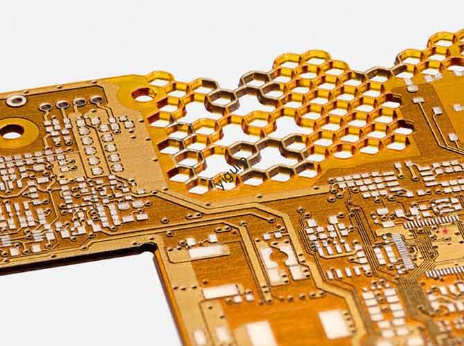
- Heat dissipation holes: Use a mesh pattern with holes at least 1mm wide. This prevents dust from blocking airflow.
- Interface placement: Make sure USB ports or DC jacks are positioned to align perfectly with the circuit board inside. A misalignment of 0.5mm can make assembly impossible.
- Mechanical Design (MD) : Focus on the internal structure.
- Screw hole placement: Space mounting holes for the circuit board 20-30mm apart for even support.
- Draft angles: For parts that will be CNC machined, add a 1-degree draft angle to vertical walls. This helps with tool access and prevents parts from sticking.
- DFMEA Analysis: Think about what could go wrong.
- Heat simulation: Use software like ANSYS to check if any component might exceed 85°C during use. This is a common limit for power components.
- EMI protection: Design spaces for shielding around transformers to prevent them from interfering with other electronics.
Step 2: Machining Execution: How Do You Choose the Right Method?
Pick the method that matches your prototype’s purpose and quantity.
| Your Goal | Best Method | Why? |
|---|---|---|
| Check the look and fit of a phone charger (1-5 units) | 3D Printing (Resin) | Fast, cheap, and captures fine details like logos and button textures. |
| Test the electrical performance of a battery protection board (5-20 units) | CNC Machining (Aluminum or POM) | High precision and durable materials. The prototype will survive repeated plugging and testing. |
| Get 30 units of a power module for customer feedback | Silicone Duplication (PU Resin) | Much cheaper than making 30 CNC parts. Each copy preserves the master’s details. |
Step 3: Surface Treatment: How Do You Enhance the Prototype?
Treatments improve both the look and the function of power prototypes.
| Treatment | Purpose | Power-Specific Use |
|---|---|---|
| Spraying | Adds color, provides insulation, resists fingerprints. | Matte black coating on a charger shell to hide scratches. Insulating paint inside an enclosure to prevent shorts. |
| Plating | Stops corrosion, improves conductivity. | Anodizing an aluminum heat sink to prevent rust. Nickel plating on copper connectors to stop oxidation. |
| Texture | Improves grip, adds branding. | Laser-engraved grip patterns on the sides of a charger. Silk-screened voltage specs like “5V/2A” on the case. |
Step 4: Assembly and Functional Testing: Does It Actually Work?
This is the most important step. A power prototype must be tested under real conditions.
How Do You Assemble the Prototype?
- Gather all parts: You’ll need the circuit board (PCBA), transformer, heat sink, cables, and small screws (often M2 or M3 size).
- Mount internal parts: Secure the circuit board inside the enclosure with screws. Make sure it doesn’t touch any metal parts that could cause a short circuit.
- Attach the heat sink: Apply a thin layer of thermal paste (about 0.1mm thick) between the heat-generating chip and the heat sink. This improves heat transfer.
- Install the interfaces: Push the USB port through its cutout in the shell. Solder its cables to the circuit board. A weak solder joint can cause a voltage drop later.
What Critical Tests Must You Perform?
| Test Type | How to Do It | What Is a Pass? |
|---|---|---|
| Electrical Performance | Use a multimeter to measure output voltage and current. Simulate an overload (120% of normal current) and a short circuit. | Output voltage is within ±5% of the rating (e.g., 5V output reads between 4.75V and 5.25V). Overload protection kicks in within 1 second. |
| Heat Dissipation | Run the power supply at full power for 2 hours. Use an infrared thermometer to check temperatures. | No component exceeds 85°C. The outside case surface stays below 45°C (safe to touch). |
| Structural Durability | Plug and unplug a cable 1000 times. Drop the prototype from 1 meter onto a hard floor. | No internal parts come loose. The shell doesn’t crack open, exposing live circuits. |
What Are the Best Practices for Power Prototype Machining?
These tips help you avoid common mistakes.
How Do You Choose the Right Material for Power?
Match the material to the part’s job.
| Material | Key Properties | Best For |
|---|---|---|
| Aluminum Alloy (6061) | Light, conducts heat well (167 W/m·K), resists rust. | Heat sinks, metal cases for high-power modules. |
| ABS Plastic | Tough, resists heat up to 90°C, easy to machine. | Charger shells, brackets to hold circuit boards. |
| POM (Acetal) | Wear-resistant, low friction. | Moving parts like folding charger hinges or sliding covers. |
| Silicone | Soft, grippy, handles -50°C to 200°C. | Sealing rings for waterproof modules, soft grip covers. |
| Resin (for 3D printing) | High precision, smooth surface, insulates electricity. | Clear prototypes to show off indicator lights, early look-and-feel models. |
How Do You Control Precision for Safety and Performance?
- Heat dissipation holes: Machine them with CNC for consistent size and placement. Holes should be at least 1mm wide and spaced 5-10mm apart for good airflow.
- Screw holes: Use CNC drilling to get the depth and position exactly right. Hole position should be accurate to ±0.1mm to align with the circuit board. Drilling too deep can damage the internal cavity.
- Interface cutouts: Leave a small 0.1mm gap around the connector. This makes it easy to insert without being too loose.
How Do You Troubleshoot Common Machining Problems?
| Problem | Likely Cause | How to Fix |
|---|---|---|
| 3D-printed shell warps | PLA shrinks as it cools. The bed might be uneven. | Use a heated bed at 60°C. Enclose the printer to keep temperature steady. Add thin reinforcement ribs (1-2mm) to the design. |
| CNC aluminum has burrs on fins | Tool is dull. Feed rate is too fast. | Replace with a sharp carbide end mill. Reduce feed rate by 20%. Use a deburring tool to clean up edges. |
| Silicone-duplicated parts have air bubbles | No vent holes in the mold. Resin poured too fast. | Drill small 1-2mm vent holes at the highest points of the mold. Pour resin slowly (about 1-2ml per second). Tap the mold gently to shake bubbles loose. |
Conclusion
Power prototype machining is a specialized process focused on safety and reliability. It’s not just about making a shape; it’s about proving a product that handles electricity and heat will work. Start with a solid design that considers heat flow and component placement. Choose your machining method based on your goal: 3D printing for fast look-and-feel models, CNC machining for strong, precise functional parts, and silicone duplication for cost-effective small batches. Apply the right surface treatments, like anodizing for heat sinks or insulating paint for enclosures. Finally, put the assembled prototype through rigorous tests: check its electrical output, measure temperatures under load, and test its physical durability. By following this workflow, you create a power prototype that truly validates your design and reduces the risk of failure in production.
FAQ
Can I use 3D printing for a high-power prototype like a 60W industrial power supply?
You can use 3D printing for the appearance model of the case. But for functional testing of a 60W unit, you need a different method. High power generates significant heat (often over 80°C), which can melt a PLA or ABS plastic shell. For functional testing, you need a CNC-machined aluminum heat sink and possibly a heat-resistant plastic like POM for other parts to ensure the prototype survives.
How long does it take to machine a prototype for a 5V/2A charger?
The timeline depends on the method:
- 3D printing: About 8-12 hours, including printing and removing supports.
- CNC machining: About 1-2 days, which includes programming the machine and the actual cutting time.
- Silicone duplication: About 3-5 days, as making the mold takes time.
You should also add 1-2 days for final assembly and testing.
What’s the most cost-effective way to get 20 units of a custom power supply enclosure?
Silicone duplication is usually the best choice. First, make one high-quality master prototype using 3D printing (cost about $20-$50). Then, use that master to make a silicone mold and cast 20 copies in PU resin (cost about $3-$15 each). Your total cost might be $80-$225. Machining 20 separate units on a CNC machine would likely cost $150-$400 or more, as each unit requires significant machine time.
Discuss Your Projects with Yigu Rapid Prototyping
Need a reliable power prototype for your next electronic product? At Yigu Rapid Prototyping, we specialize in all the methods you’ve read about. Whether you need a fast 3D-printed model to check the feel of a charger, a precision CNC-machined aluminum heat sink for thermal testing, or a small batch of silicone-duplicated cases for user trials, we can help. Our team in Shenzhen understands the unique demands of power products, from heat dissipation to safety spacing. We guide you to the right material and process for your specific needs. Contact us to discuss your project and get a detailed quote.