Introduction
If you have ever wondered how precision parts—from the sleek metal case of your smartphone to the complex components inside a jet engine—get their detailed shapes, the answer often lies in milling. But you might be asking: What exactly is the milling manufacturing process, and how does it work for different materials? At its core, milling is a subtractive manufacturing method. It uses rotating cutting tools, called endmills, to remove material from a solid workpiece. This creates custom shapes, holes, slots, or surfaces. Unlike drilling, which only makes round holes, or turning, which spins the workpiece, milling spins the cutting tool while the workpiece moves. This allows it to create complex 2D or 3D features with incredibly tight tolerances, often as small as ±0.001 inches. Whether you are a hobbyist with a desktop CNC mill or a manufacturer scaling up for production, this guide breaks down everything you need to know. You will learn the basics of how milling works, how to choose the right tools, how to avoid common mistakes, and understand current industry trends. By the end, you will have the knowledge to tackle milling projects with confidence.
What Are the Core Principles of Milling?
Before diving into different techniques, it is critical to understand the basic mechanics of milling. Small misunderstandings here can lead to wasted material or poor-quality parts.
Key Components of a Milling System
Every milling setup relies on four core parts, and each one plays a vital role in achieving precision.
- Milling Machine: This is the base unit that holds the cutting tool and the workpiece. Machines range from small benchtop models for hobbyists, costing between $500 and $5,000, to large industrial CNC mills for mass production, which can cost anywhere from $50,000 to over $500,000.
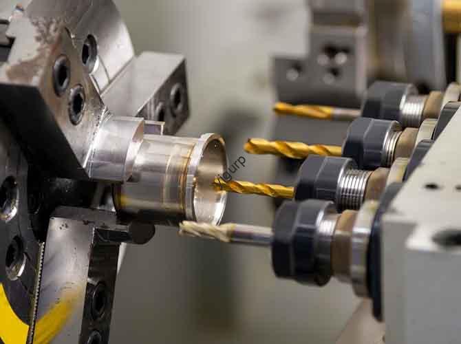
- Endmill: This is the rotating cutting tool itself. Unlike a drill bit, which has a pointed tip for cutting straight down, an endmill has cutting edges on its sides and often on its tip. This allows it to cut in multiple directions—sideways, downwards, and even in curves.
- Workholding Device: These are the clamps, vises, or chucks that securely hold the workpiece in place. Poor workholding causes vibration, which ruins precision. Industrial setups often use vacuum chucks or custom jigs for maximum stability.
- Control System: On a manual mill, this is simply a hand crank that you turn to move the table. On a CNC mill, it is a computer program, written in a language called G-code, that automates all the tool movements. CNC control allows for perfect repeatability, meaning you can produce 100 identical parts as easily as you can produce one.
The Milling Process in 5 Simple Steps
While CNC milling adds automation, the basic workflow is consistent for any type of milling.
- Prepare the Workpiece: Cut your raw material—whether it is metal, plastic, or wood—to a rough size, leaving a little extra material (about 1-5mm) for the milling process. Clean it to remove any oil or debris.
- Secure the Workpiece: Clamp the workpiece firmly to the mill’s table using a vise or chuck. For delicate parts, like thin plastic, use soft jaws to avoid damaging them.
- Set Up the Endmill: Install the correct endmill for your job, such as a flat-end mill for cutting slots or a ball-end mill for curved surfaces. Then, align the tip of the tool with a known starting point on the workpiece. This is called “zeroing” the machine.
- Program or Adjust Settings: For a CNC mill, you load a G-code program that tells the machine the exact toolpath, speed, and feed rate. For a manual mill, you set the spindle speed (RPM) by hand and then use the hand cranks to move the table and guide the cut.
- Start Milling: Turn on the spindle to start the tool rotating, and begin removing material. It is good practice to pause occasionally to check for any signs of tool wear or damage to the workpiece.
Real-World Example: A small automotive parts shop uses a CNC mill to make aluminum brackets. Their process is simple and efficient. They cut 6061 aluminum into 100x100mm blocks, secure them with a vacuum chuck, use a 10mm flat-end mill, and run a 15-minute G-code program. The result is 50 identical brackets per hour, each with a tolerance of ±0.002 inches—far more precise than any manual method could achieve.
What Are the Different Types of Milling Manufacturing Processes?
Not all milling is the same. Different techniques are used depending on the part’s shape, the material, and the level of precision required.
Face Milling vs. Peripheral Milling
These are the two primary categories of milling, and they are distinguished by how the endmill interacts with the workpiece.
| Type | How It Works | Best For | Tool Used | Key Advantage |
|---|---|---|---|---|
| Face Milling | The face (the top surface) of the endmill cuts the top of the workpiece to create a flat, smooth surface. | Smoothing the top of a block, like an aluminum plate for an electronic device. | Face mill (has multiple cutting teeth on its face). | Fast material removal. Can achieve very smooth finishes, as good as Ra 0.8 μm. |
| Peripheral Milling | The side edges of the endmill do the cutting, creating slots, grooves, or vertical walls. | Making slots in a gear or cutting channels in a plastic housing. | Flat-end mill or ball-end mill. | Creates complex 2D shapes. Ideal for deep cuts, up to 5 times the endmill’s diameter. |
Case Study: A medical device manufacturer uses both techniques. They use face milling to create a perfectly smooth surface on titanium implant bases, which requires a finish of Ra 0.4 μm to meet strict FDA standards. Then, they use peripheral milling to cut the precise 2mm-wide slots where the screws will go.
CNC Milling vs. Manual Milling
The choice between automated and manual milling depends on how many parts you need to make and how complex they are.
- Manual Milling: The machine is controlled by hand cranks, with no computer involved. It is best for very small batches of 1-10 parts or for simple shapes, like a single wooden bracket. The pros are that it is low cost, with entry-level machines under $2,000, and it is easy to learn. The cons are that it is slow (maybe 1-2 parts per hour), less precise (tolerances of about ±0.01 inches), and prone to human error.
- CNC Milling: The process is automated via G-code. It is best for large batches of 100+ parts or for complex 3D shapes, like a smartphone’s metal frame. The pros are that it is fast (20-100 parts per hour), highly precise (down to ±0.0005 inches), and perfectly repeatable. The cons are the high upfront cost and the need to learn G-code or CAM software.
Key Data: According to the Manufacturing Technology Insights 2024 report, 78% of manufacturers now use CNC milling for production, up from 55% in 2019. This shift is driven by its ability to reduce labor costs by 40% and material waste by 25%.
2D vs. 3D Milling
This distinction refers to the complexity of the part’s geometry.
- 2D Milling: The cutting tool moves only in two axes, X and Y, to cut flat features like slots or holes. It is used for simple parts, such as a flat plastic spacer with a couple of holes.
- 3D Milling: The tool moves in all three axes, X, Y, and Z, to create curved or contoured surfaces. It is used for complex parts like a turbine blade or a sculpted guitar neck.
Pro Tip: For 3D milling, you should always use a ball-end mill. Its rounded tip creates smooth curves without leaving sharp “stepped” marks, which is what would happen if you tried to use a flat-end mill on a curved surface.
What Are the Critical Factors for Successful Milling?
Even with the best equipment, a milling job can fail if you ignore these key variables. Mastering these four factors is essential.
1. Choosing the Right Endmill
The endmill is the heart of the milling process. Pick the wrong one, and you will get poor cuts or broken tools. You need to consider three things:
- Material Compatibility: Use high-speed steel (HSS) endmills for wood or plastic. They are low cost and easy to sharpen. For cutting metals like aluminum, steel, or titanium, you must use carbide endmills. They are much harder and resist the heat generated by machining metal better than HSS.
- Number of Flutes: The flutes are the spiral grooves on the endmill that carry away the chips of removed material. Use 2-flute endmills for soft materials like wood and plastic. The large gaps between the flutes clear chips quickly, preventing clogging. Use 4- or 6-flute endmills for metals. More flutes give a smoother cut, but they require slower feed rates to avoid overheating.
- Coating: Special coatings reduce friction and help the tool last longer. For aluminum, an aluminum titanium nitride (AlTiN) coating is great because it resists heat up to 600°C. For steel, a titanium carbonitride (TiCN) coating is a good choice.
Example: A machinist once tried using a 2-flute HSS endmill to cut stainless steel. After just 5 minutes, the tool overheated and became dull. By switching to a 4-flute carbide endmill with a TiCN coating, he was able to machine 50 parts before the tool needed to be changed.
2. Spindle Speed and Feed Rate
Spindle speed (how fast the endmill spins, in RPM) and feed rate (how fast the workpiece moves into the tool) are two sides of the same coin. Getting them wrong causes problems.
- Speed too high: The endmill overheats, leading to rapid wear or, for plastics, melting.
- Speed too low: You get a rough surface finish and the process takes too long.
- Feed rate too high: You risk breaking the endmill, especially with brittle materials.
- Feed rate too low: The tool doesn’t cut effectively; it just rubs against the material. This creates friction and heat, which is bad for both the tool and the part.
The right spindle speed is calculated with a formula: RPM = (Cutting Speed × 12) / (π × Endmill Diameter) . The cutting speed is a standard value based on the material. For example, using a 0.5-inch carbide endmill on aluminum (cutting speed of 400 SFM), the calculation would be: RPM = (400 × 12) / (3.14 × 0.5) ≈ 3,057 RPM.
3. Workholding
Poor workholding is the number one cause of milling errors. If the workpiece moves even a tiny bit, your part will be ruined.
- Secure Tightly: The workpiece must not move at all. For metal, use a heavy-duty vise with serrated jaws. For flat parts like plastic sheets, a vacuum chuck is excellent.
- Distribute Pressure Evenly: For large parts, use multiple clamps. Be careful not to apply too much pressure in one spot, as this can warp thin materials.
- Avoid Blocking the Tool Path: This is a common beginner’s mistake. Make sure your clamps are positioned so that the endmill has a clear path to cut all the features you need.
4. Coolant and Lubrication
Coolant helps reduce heat and friction, which extends tool life and improves the surface finish. The right choice depends on the material.
- Metal Milling: Use a water-soluble coolant for aluminum and steel, or an oil-based coolant for tougher materials like titanium. Using coolant can increase tool life by 50% to 100%.
- Wood/Plastic Milling: Do not use liquid coolant. Instead, use a strong blast of compressed air to clear away chips. Liquid coolant can warp wood and can cause some plastics to melt or craze.
What Are Common Milling Problems and How Do You Fix Them?
Even experts run into problems. Here are the top five issues, their causes, and how to fix them.
- Rough Surface Finish: This is often caused by a dull endmill, a feed rate that is too high, or vibration from a loose workpiece. The fix is to replace the endmill, reduce the feed rate by about 20%, and re-tighten the workpiece.
- Endmill Breakage: This usually happens because the feed rate is too high, the spindle speed is too low, or the tool has crashed into a clamp. To fix it, lower the feed rate, increase the RPM to the recommended value, and double-check your toolpath for any obstacles.
- Workpiece Warping: This is common with thin materials. It can be caused by too much clamping pressure or by heat buildup. The solution is to use soft jaws to hold the part or reduce the clamping pressure. If heat is the issue, make sure you are using enough coolant.
- Inaccurate Dimensions: If your part is not the right size, the problem could be incorrect zeroing of the tool, a worn-out endmill, or a machine that needs calibration. Re-zero your tool, replace the endmill, and check your machine’s calibration.
- Chip Clogging: When chips get stuck in the flutes, they can ruin the cut. This can happen if you are using a 2-flute endmill on metal, or if your spindle speed is too low. The fix is to switch to a 4-flute endmill for metal, increase the RPM, and use compressed air or coolant to help clear the chips.
Conclusion
The milling manufacturing process is a powerful and versatile method for creating precision parts from a huge range of materials. At its heart, it is a subtractive process where a rotating endmill cuts away material from a solid block. Understanding the core components—the machine, the tool, the workholding, and the control system—is the first step to success. By learning the differences between techniques like face milling and peripheral milling, or manual and CNC control, you can choose the right approach for any project. And by mastering critical factors like tool selection, speeds and feeds, and workholding, you can avoid common problems and produce high-quality parts with confidence.
FAQ
What materials can be milled?
Nearly any solid material can be milled. This includes common metals like aluminum, steel, titanium, and brass. It also includes a wide range of plastics like ABS, PVC, and polycarbonate, as well as wood, composites like carbon fiber, and even some ceramics with specialized endmills.
How much does a milling machine cost?
The cost varies widely depending on the type and size. A small, benchtop manual mill for hobbyists can cost between $500 and $2,000. A benchtop CNC mill suitable for small batch production ranges from $3,000 to $15,000. For high-volume industrial production, a large CNC mill can cost anywhere from $50,000 to over $500,000.
What’s the difference between a mill and a router?
While they look similar, they are designed for different tasks. Routers are generally smaller, use very high spindle speeds (10,000–30,000 RPM), and are best for cutting soft materials like wood, plastic, and composites. Mills are larger, more rigid machines that use lower spindle speeds (1,000–10,000 RPM) but generate much more torque. This allows them to cut hard materials like steel and titanium with high precision.
How long does it take to learn milling?
Learning the very basics of manual milling, like how to cut a simple slot or drill a hole, can take just 1-2 weeks. Learning to use a CNC mill, including designing parts in CAD software and generating toolpaths in CAM software, can take 1-2 months to become proficient for simple parts. Mastering advanced techniques like 3D milling or working with difficult materials like titanium can take 6 months or more of dedicated practice.
Discuss Your Projects with Yigu Rapid Prototyping
Are you ready to start your next milling project? Whether you need a single, complex prototype or a full production run of precision parts, the team at Yigu Rapid Prototyping has the expertise and the advanced CNC machinery to deliver exceptional results. We work with a wide range of materials and can help you optimize your designs for manufacturability, saving you time and money.
Contact Yigu Rapid Prototyping today to discuss your project. Upload your design files for a free, expert quote and design review. Let’s build something great together.