Creating a physical model of a metal part sounds simple. But a plastic 3D-printed bracket won’t tell you if your aluminum design can survive real-world stress. That’s where making hardware prototypes comes in. It’s the process of building functional, metal-based models to test if your product actually works before you spend thousands on molds and production lines. This isn’t about quick look-alikes. It’s about verifying strength, fit, and material behavior. This article walks you through the entire workflow, from defining your goals to choosing the right process and inspecting the final part. You’ll learn how to avoid common pitfalls and ensure your prototype sets you up for mass-production success.
What Are the Core Goals of Making Hardware Prototypes?
Before you touch any metal, you need a clear purpose. Your goal dictates the material, process, and budget.
Why Is Functional Verification the Top Priority?
The main reason to build a hardware prototype is to see if the part does its job.
- Load-bearing test: Does that aluminum drone bracket bend when the motors spin up? A prototype lets you mount it and find out.
- Assembly fit: Will that copper connector slide into the circuit board snugly? You can test the tolerance.
- Movement check: Do the hinges on a stainless steel latch move smoothly? You can feel the action.
Real example: A client designed a bracket for a heavy industrial sensor. The CAD looked perfect. We machined a prototype from 6061 aluminum. When they bolted it on, the thin wall flexed too much. We caught it, redesigned that wall, and made a new prototype. Fixing it cost a few hundred dollars. Fixing it after die-casting would have cost ten thousand.
How Does Appearance Confirmation Help?
For consumer products, how it looks matters as much as how it works.
- Finish match: Does the brushed metal finish on your stainless steel smartwatch case look premium enough? The prototype shows you.
- Color accuracy: Will that anodized red on your aluminum camera body match your brand guidelines? You can hold it in your hand and decide.
- Ergonomics: Does the curve of a medical tool handle feel right in the palm? A metal prototype feels closer to the real thing than plastic.
What Does Assembly Testing Reveal?
A part rarely lives alone. It must play nice with others.
- Screw fit: Do the threads you cut in the aluminum part engage properly with the mating screw? Test it.
- Component interface: Does the copper heat sink make full contact with the chip it’s meant to cool? You can apply thermal paste and check.
- Tolerance stack-up: When you put five parts together, do the gaps add up to a problem? A full assembly prototype is the only way to know.
When Do You Need Material Validation?
Sometimes, the question isn’t about shape—it’s about the stuff itself.
- Corrosion test: Will this 316 stainless steel part really resist saltwater in a marine sensor? You can put the prototype in a salt spray chamber.
- Heat resistance: Will this aluminum alloy heat sink dissipate enough power? You can attach a heater and measure temperatures.
- Wear check: Will the teeth on this steel gear wear down after 10,000 cycles? A prototype lets you run a test.
What Is the Step-by-Step Workflow?
Building a metal prototype follows a logical path. Skipping steps leads to rework.
Design Stage: How Do You Lay the Foundation?
Start with a clear plan on paper (or screen).
- Analyze needs: Write down exactly what the part must do. What material is needed? Aluminum for light weight? Stainless steel for rust resistance? What accuracy is critical? Maybe a hole position needs ±0.05mm, but the outer edge can be ±0.1mm.
- Create the 3D model: Use CAD software like SolidWorks or Fusion 360. Model every feature.
- Make detailed drawings: Don’t just send the 3D file. Create 2D drawings that clearly mark all critical tolerances and surface finishes (like Ra 1.6 for a sealing surface).
Material & Process Selection: How Do You Match to Your Goals?
This is where you choose the recipe for your part.
Which Material Should You Pick?
| Material | Best Properties | Good For |
|---|---|---|
| Aluminum Alloy (6061, 6063) | Light, easy to machine, cheap | Shells, brackets, housings (drone frames, laptop cases) |
| Stainless Steel (304, 316) | Strong, rust-proof | Precision parts, outdoor gear (sensors, medical tools) |
| Copper / Brass | Conducts heat/electricity well | Connectors, heat sinks (phone ports, CPU coolers) |
| Carbon / Alloy Steel | Very strong, wear-resistant | Gears, bushings, load-bearing brackets |
Which Process Fits Your Part?
| Method | Best For | Example Part |
|---|---|---|
| CNC Machining | Complex 3D shapes, high precision, any batch size | An aluminum drone hub with threaded holes |
| Stamping / Sheet Metal | Thin parts (under 3mm), simple shapes, large batches | A stainless steel laptop cover |
| Metal 3D Printing (SLM) | Impossible geometries (internal lattices), one-offs | A titanium medical implant with porous structure |
| Welding / Assembly | Joining multiple parts into one | Welding two aluminum brackets for a frame |
Production: How Do You Build It?
Let’s look at the two most common methods in detail.
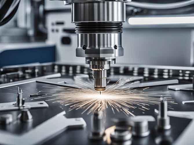
How Does CNC Machining Work for Prototypes?
This is the go-to method for precision metal parts.
- Program the path: The 3D model is converted into toolpaths (G-code). The programmer decides which tools to use—a flat end mill for flat surfaces, a ball end mill for curves.
- Set up the machine: The metal block is clamped tightly. The tool’s starting position is set precisely, often with an automatic probe.
- Rough cutting: The machine quickly removes most of the excess material, leaving about 0.5mm of “meat” for the final pass.
- Finish cutting: The machine runs slower, taking off that last 0.5mm to achieve the final shape and smooth surface.
- Deburr and clean: A technician files off any sharp edges. The part goes into an ultrasonic cleaner to remove all oil and metal chips.
How Does Stamping Work for Thin Parts?
For thin metal sheets, stamping is efficient, especially for larger quantities.
- Cut the blank: A laser cutter or wire EDM cuts the basic shape from a sheet of metal, say 1.5mm thick 304 stainless.
- Form the shape: A punch press with a die bends the flat blank into its final 3D shape—like folding a paper into a box, but with tons of force.
- Join if needed: If the design has multiple pieces, they are welded or riveted together.
- Finish: Weld seams are ground smooth.
Surface Treatment: How Do You Enhance the Part?
Treatments make the part look right and perform better.
| Treatment | Typical Process | What It Does |
|---|---|---|
| Spraying | Sandblast -> Primer -> Paint -> Bake | Adds color (like matte gray), protects from scratches |
| Electroplating | Clean -> Acid -> Nickel/Chrome plate -> Polish | Gives a shiny, reflective finish, resists rust |
| Anodizing (for Aluminum) | Electrolytic bath | Adds a hard, colored layer (black, silver, red), resists wear |
| Laser Engraving | Laser burns surface | Adds permanent text, logos, or QR codes |
Quality Inspection: How Do You Know It’s Right?
Inspection is non-negotiable. It proves the prototype meets the spec.
- Check dimensions: Use a CMM (Coordinate Measuring Machine) or micrometer to measure critical holes and surfaces. Is that hole within ±0.05mm?
- Test function: Assemble it with other parts. Does it fit? Move a hinge. Does it swing freely? Apply a load. Does it hold?
- Look it over: Check the surface under good light. Are there scratches? Is the color consistent? Use a gloss meter if the finish spec is critical.
What Are Common Problems and How Do You Fix Them?
Even experienced teams hit snags. Here’s how to handle them.
| Problem | Likely Cause | How to Fix |
|---|---|---|
| Part warps during machining | Internal stress in the metal releases as you cut it away. | Use annealed (heat-treated) metal stock. Adjust the cutting path to remove material more evenly. |
| Surface is too rough | Tool is dull, or cutting speed/feed is wrong. | Replace the cutting tool. Increase spindle speed or slow down the feed rate for the final pass. |
| Weld looks bad (holes, weak joint) | Welding settings are off, or the parts weren’t held steady. | Adjust welding current/speed. Use a fixture to hold parts perfectly still during welding. |
What Are the Advantages and Limitations?
Weigh these pros and cons before starting.
Advantages
- Real material properties: The prototype behaves like the final part. You learn about strength, heat, and corrosion.
- High precision: You can hold tight tolerances, down to ±0.05mm or better.
- Realistic finish: Surface treatments like anodizing and plating let you match the final product’s look.
Limitations
- Higher cost: Machining or making a simple stamping die costs more than 3D printing a plastic part.
- Slower than plastic: It takes 1-2 weeks, compared to a few days for a simple resin print.
- Not cheap for one part: The cost per piece is high for low quantities.
What Are Real-World Examples?
Hardware prototyping is essential across many fields.
- Mechanical equipment: Testing the fit of a steel gear on a shaft, or the wear life of a bronze bushing.
- Consumer electronics: Checking the heat from a prototype aluminum heat sink, or the strength of a stainless steel phone bracket.
- Medical devices: Evaluating the feel of a stainless steel surgical handle, or the biocompatibility of a titanium implant.
- Automotive: Verifying the assembly of lightweight aluminum interior parts, or the corrosion resistance of exterior stainless steel trim.
Conclusion
Making hardware prototypes is about de-risking your product. It’s the step where you prove your metal part can survive the real world. Start by defining your core goal: Are you testing strength, fit, appearance, or material behavior? Choose your material based on those needs—aluminum for light weight and cost, stainless steel for corrosion resistance. Select a process that fits your part’s complexity and quantity—CNC machining for precision and complex shapes, stamping for thin parts in larger batches. Follow a disciplined workflow: design, produce, treat, and inspect. Watch for common issues like warping or poor surface finish, and know how to fix them. Yes, it costs more and takes longer than plastic prototyping. But the insight you gain about your metal product’s real performance is invaluable. It’s an investment that prevents expensive failures in mass production.
FAQ
Can we use 3D printing (plastic) instead of hardware prototyping for metal parts?
No, not if you need to verify performance. A plastic prototype cannot replicate the strength, conductivity, or heat resistance of metal. A plastic drone bracket might fit, but the real aluminum one could bend under load. You need a metal prototype to test real-world behavior.
How long does making a hardware prototype take?
It depends on complexity and process. A simple CNC-machined aluminum bracket typically takes 5 to 7 days. A complex stamped stainless steel part that needs anodizing might take 10 to 14 days. This is longer than plastic printing, but necessary for accuracy.
What’s the most cost-effective material for hardware prototypes?
Aluminum alloy (6061 or 6063) is usually the cheapest and easiest to machine. It’s perfect for functional testing of brackets, housings, and structural parts, especially indoors. Stainless steel (304) costs more but is essential for parts needing corrosion resistance, like medical or marine components.
Discuss Your Projects with Yigu Rapid Prototyping
Ready to turn your metal part design into a real, testable prototype? At Yigu Rapid Prototyping, we specialize in precision hardware prototyping. Whether you need a CNC-machined aluminum drone frame, a stamped stainless steel enclosure, or a copper heat sink for testing, we guide you to the right material and process. Our team in Shenzhen offers fast turnaround, clear communication, and strict quality checks. We help you catch design flaws early, saving time and money before mass production. Contact us to discuss your project and get a detailed quote.