Introduction
Die casting cold material destroys parts from the inside out. It happens when molten metal cools too much before filling the mold, losing the fluidity needed to reach every corner. The result? Rough surfaces, internal voids, and structural weakness. Scrap rates can hit 20% in severe cases. For automotive engine parts or aerospace components, cold material creates safety risks that cannot be ignored. This guide explains exactly what cold material is, why it forms, and how to eliminate it with systematic temperature control, better mold design, and optimized process parameters.
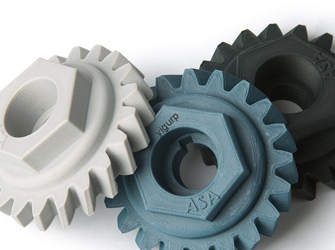
What Exactly Is Die Casting Cold Material?
Basic definition
Cold material is a defect where molten metal experiences excessive cooling during melting, transfer, or mold filling. The metal loses heat too quickly, reducing its fluidity. It solidifies prematurely or forms irregular structures that fail to bond properly with surrounding metal.
Unlike surface scratches or dents, cold material is often a hidden threat. It may appear as minor surface marks but hide internal flaws like shrinkage voids or pore clusters deep inside the part.
What it looks like
On the surface, cold material shows as:
- Rough, dull patches with no metallic luster
- Flow lines or layered striations that look like frozen waves
- Localized material shortage—small gaps where metal never reached
Inside the casting, you find:
- Concentrated shrinkage voids of 0.1-0.5mm diameter
- Aggregated pores clustered near cold material areas
- Unmelted solid particles—residues from incomplete melting
X-ray inspection or metallographic analysis reveals these internal defects. A sample etched with 5% nitric acid shows the structure clearly under magnification.
Where it forms
Cold material targets specific areas:
Thin-walled sections far from the gate lose heat fastest. A 1mm aluminum shell 100mm from the gate is 3x more likely to develop cold material than a 5mm section near the gate.
Deep cavity bottoms take longer to fill. Metal sits against cold mold walls, cooling before filling completes.
Low-temperature mold zones act as heat sinks. Areas near cooling channels or without proper preheating suck heat from the metal.
What Causes Cold Material?
Temperature control failures
Incomplete melting leaves unmelted particles in the metal. These act as “cold cores” that reduce overall fluidity.
Holding furnace issues let temperature drop 20-30°C. Cooled metal solidifies at the flow front, blocking further filling.
Unpreheated pressure chambers absorb heat from the first metal. At room temperature instead of 150-200°C, the chamber causes front-end solidification in 2-3 seconds.
A real example: An aluminum ADC12 plant had a faulty holding furnace. Metal temperature dropped from 700°C to 650°C. Cold material defects jumped from 3% to 18% in one week.
Mold design problems
Poor runner design with sudden cross-section changes or sharp bends increases flow resistance. Filling takes longer. Heat loss increases.
Uneven mold temperature from cooling channels too close to the cavity (<5mm) creates cold spots. Metal contacting these areas cools below its liquidus and stops flowing.
Excessive release agent over 0.1mm thick acts as an insulator. It prevents heat transfer from mold to metal, making cooling worse.
A zinc toy manufacturer had a 90° sharp bend in their runner. Cold material formed at the bend in 25% of castings. Redesigning to a 15mm radius cut defects to 2%.
Process parameter mismatches
Slow injection speed under 2 m/s for aluminum extends contact time with cold mold. More time means more cooling.
Incorrect pressure holding timing compresses partially solidified metal, creating layered cold material.
Excessive pouring volume leaves residual cold material in the chamber. This mixes with new hot metal, reducing overall temperature.
An automotive plant used 1.5 m/s injection speed for 2mm aluminum brackets. 30% had cold material. Increasing speed to 4 m/s eliminated the defect.
Material issues
Alloy composition deviation hurts fluidity. Aluminum with silicon below 9% instead of 11-13% loses flow capacity. Silicon is the “flow enhancer.”
Unscreened return material brings oxide scales and impurities. These act as nucleation sites for premature solidification.
A magnesium plant mixed 50% unscreened return material with new ingots. Cold material rose by 12% . Reducing return to 30% and adding a 50μm filter cut defects to 4%.
| Cause Category | Specific Failure | Impact |
|---|---|---|
| Temperature | Furnace drops 20-30°C | Defects 3% → 18% |
| Mold design | 90° sharp bend | 25% scrap |
| Process | 1.5 m/s speed | 30% cold material |
| Material | 50% unscreened return | +12% defects |
How Do You Eliminate Cold Material?
Step 1: Build precise temperature control
Melting stage: Use a double-furnace process. Main furnace at 720-750°C for full melting. Auxiliary furnace at 680-710°C for precise adjustment to the upper process limit.
Install online infrared thermometers with ±2°C accuracy. Trigger an alarm if temperature drops below the lower limit—670°C for ADC12.
Transfer stage: Use heated transfer ladles with 5kW electric heaters. Maintain metal temperature during transport. Keep heat loss under 5°C .
Injection stage: Preheat the pressure chamber to 150-200°C for aluminum, 180-220°C for magnesium. Use electric heating jackets. Never start with a room-temperature chamber.
Mold preheating: Set gradient temperatures. Aluminum molds at 200-250°C. Magnesium molds at 220-280°C. Use zone-specific heating for deep cavities. Keep temperature deviation under ±10°C .
Step 2: Optimize mold design
Runner redesign: Replace sudden cross-section changes with gradual transitions of 1-3° taper. Use smooth curved runners with radius ≥10mm. This cuts filling time by 30% and heat loss by 25% .
Add buffer grooves at thin-walled entrances with volume 1.2× runner volume. They stabilize flow and prevent front-end cooling.
Thermal balance: Embed ceramic heat-insulating inserts in thin-walled or deep cavity areas. Thermal conductivity of 0.5 W/m·K slows heat dissipation by 50% .
Keep cooling channels at least 8mm from cavity surface, not 5mm. This prevents over-cooling.
Surface maintenance: Polish cavity surfaces to Ra ≤0.8 μm with diamond wheels. Smooth surfaces reduce friction and heat loss from metal-mold contact.
Control release agent with mist sprayers. Apply thin, uniform film of 5-10μm. Avoid excessive spraying that insulates the metal.
Step 3: Adjust process parameters dynamically
| Parameter | Adjustment | Target |
|---|---|---|
| Injection speed | Fast-slow-fast three-stage | Fill time ≤2 sec for parts <200mm |
| Pressure holding | Start 0.2-0.3 sec after fill | 80-120MPa, hold 70-80% of solidification time |
| Pouring volume | (Casting + Runner) × 1.05 | No residual in chamber |
Injection speed: Use three-stage control. Initial fast at 4-6 m/s to reach cavity quickly. Middle slow at 2-3 m/s for thick areas. Final fast at 3-5 m/s for thin walls.
Pressure holding: Trigger by cavity pressure sensors, not timers. Start 0.2-0.3 seconds after filling completes. Hold at 80-120MPa for 70-80% of total solidification time.
Pouring volume: Calculate exactly: (Casting Volume + Runner Volume) × 1.05 safety factor. Clean chamber every 50 shots to remove residual cold material.
Step 4: Tighten material management
Alloy composition: Test every batch with spectral analysis. For ADC12, keep silicon at 11-13% . For AZ91D magnesium, keep magnesium at 0.7-1.0% .
Add flow-enhancing elements if needed. For aluminum, 0.1-0.2% rare earth (cerium, lanthanum) improves fluidity by 15-20% .
Return material: Screen with 1mm mesh to remove oxide scales and impurities. Limit return to ≤30% mixed with 70% new ingots. Higher ratios reduce fluidity.
Refining and degassing: Use argon rotary degassing for 15 minutes at 2L/min. Reduce hydrogen to <0.15ml/100g Al. This also removes small oxide inclusions.
Let metal stand for ≥15 minutes after refining. Slag floats to top. Skim it off before pouring.
How Do You Diagnose Cold Material Quickly?
Step 1: Visual inspection
Look for rough, dull patches or flow lines. Tap the area with a small hammer. A dull sound indicates internal cold material. A clear ring means normal metal.
Step 2: Microscopic check
Take a small sample from the defective area. Polish it. Under 100x magnification, look for unmelted particles or layered structures. If present, it is cold material.
Step 3: Parameter review
Check recent data logs:
- Did metal temperature drop below process range?
- Was injection speed slower than usual?
- Did mold temperature in defect area fall below target?
What Emergency Actions Work?
If cold material appears during production:
Adjust temperature: Increase metal by 10-15°C . For ADC12, go from 680°C to 695°C. Test 10-20 samples to verify improvement.
Clean chamber: Stop production. Clean pressure chamber with steel brush to remove residual cold material. Preheat to 200°C before restarting.
Tweak parameters: Increase injection speed by 0.5-1 m/s within safe range. Reduce filling time. Do not exceed 8 m/s—that causes turbulence.
Temporary mold fix: Apply small amount of high-temperature graphite release agent to cold zones. This reduces heat loss until full maintenance.
Industry Experience: Fixing Cold Material
An automotive plant had 15% scrap from cold material in engine brackets. Temperature logs showed mold temperature dropping to 160°C in deep cavities—well below the 200°C target. Adding zone-specific electric heaters to those cavities raised temperature to 210°C. Scrap dropped to 3%.
An electronics manufacturer struggled with cold material in 1mm phone frames. Injection speed was 2 m/s. Increasing to 4.5 m/s with a fast-slow-fast profile cut filling time from 1.2 seconds to 0.6 seconds. Cold material disappeared.
A magnesium component maker used 50% return material without screening. Oxide inclusions acted as nucleation sites for cold material. Installing a 50μm ceramic filter and reducing return to 30% cut defects from 12% to 2%.
Conclusion
Die casting cold material is preventable with systematic control. It forms when temperature drops, mold design blocks flow, process parameters mismatch, or material quality suffers. Fix it by building precise temperature control—double furnaces, heated transfer, preheated chambers, zone-specific mold heating. Optimize mold design with gradual runner transitions, thermal inserts, proper cooling channel spacing, and controlled release agent. Adjust process parameters dynamically—three-stage injection speed, sensor-triggered pressure holding, exact pouring volume. Tighten material management with composition testing, screened return material, and thorough degassing. With these steps, you can hold cold material defects under 2% .
Frequently Asked Questions
Can cold material defects be repaired?
Minor surface-only cold material can be repaired with argon arc welding at 80-100A using matching alloy filler, then grinding smooth. But parts with internal cold material (shrinkage, pores) or cold material in load-bearing areas must be scrapped. Repairs cannot restore structural integrity for critical applications.
How do you distinguish cold material from cold shuts?
Cold material forms in thin-walled or far-from-gate areas with unmelted particles or layers. Cold shuts form at meeting points of two metal flows, showing a clear “seam” with no particles. Cold material causes internal weakness; cold shuts mainly affect surface appearance.
Does cold material affect mechanical properties?
Yes, significantly. An aluminum ADC12 casting with cold material loses 20-30% tensile strength (310MPa → 220MPa). Elongation drops 50% (3% → 1.5%). Fatigue life shortens 60-70% (fails at 50,000 cycles vs 150,000). Cold material parts are unsafe for critical applications.
What is the most effective single fix?
Increasing injection speed usually gives the fastest improvement. For thin-walled parts, going from 2 m/s to 4 m/s cuts filling time in half, reducing heat loss dramatically. But combine with proper temperature control for best results.
How often should I check mold temperature?
Continuously for critical parts with embedded thermocouples. For less critical production, check at startup and every 2-4 hours. Temperature drift causes defects—catch it early.
Can cold material occur in thick sections?
Rarely. Thick sections retain heat longer. But if cooling channels are too close (<5mm) or mold temperature is very low, even thick sections can develop cold material near the surface.
Discuss Your Projects with Yigu Rapid Prototyping
Ready to eliminate cold material from your die casting production? At Yigu Rapid Prototyping, we combine real-time monitoring with systematic process control to deliver defect-free parts. Our IoT sensors track temperature, injection speed, and mold condition continuously, alerting operators before defects form. We optimize mold design with gradual runner transitions, thermal inserts, and proper cooling channel spacing. Our material management includes spectral analysis, screened return material, and thorough degassing. Whether you need aluminum automotive components, magnesium aerospace parts, or zinc electronic housings, we deliver with cold material rates under 2%. Contact our team today to discuss your project and see how proper process control transforms your results.