Introduction
Building a new printer is a complex engineering challenge. It involves dozens of moving parts—gears, rollers, feeders—that must work together perfectly. The housing must be sturdy and look good. Before you invest in expensive injection molds, you need a prototype to test your design. The professional CNC machining printer prototype process is the best way to create accurate, functional parts for testing. But what does this process actually look like? This article provides a step-by-step guide. We will cover everything from the initial design and material selection to the final assembly and testing. By the end, you will understand how CNC machining brings a printer design to life.
What Design and Preparation Work Is Needed Before Machining?
Before any cutting starts, you need a complete and detailed plan. This preparation stage is critical for a smooth machining process.
Understanding Your Printer’s Requirements
First, define the core specifications of your printer. What type is it—inkjet or laser? What size? A common desktop A4 printer might be around 400mm wide, 300mm deep, and 150mm tall. You need to decide on functional layouts: how many sheets will the feeder hold? How will the paper exit tray work? The design must ensure structural stability for all the moving parts, like the gear sets and paper rollers.
Splitting the Model into Machinable Parts
A printer is too complex to machine as one piece. You must split your 3D model into individual components that can be machined separately. This typically includes:
- Housings: Upper and lower shells.
- Paper Handling Parts: The feeder, paper exit tray, and cartridge bins.
- Mechanisms: The gear sets, roller shafts, and circuit board mounts.
When splitting the model, you must ensure each part has no internal features that a CNC tool cannot reach.
Creating Detailed 3D Models
Using CAD software like SolidWorks, you create precise 3D models for every part. You need to highlight critical features. For gears, you define the tooth profile (module 0.5 to 1) . For feeder rollers, you model the drive grooves (2-3mm deep) . For the circuit board, you add mounting holes (3-4mm in diameter) . It is also wise to add small draft slopes (3 to 5 degrees) to the housing walls. This makes the part compatible with future injection molding processes.
Selecting the Right Materials
Choose materials based on each part’s function, how easy it is to machine, and its cost. Think about how it will be made in mass production.
| Component | Recommended Material | Key Reason |
|---|---|---|
| Housings & Feeders | ABS Plastic | Low cost, easy to machine, and impact-resistant. |
| Gear Shafts & Brackets | Aluminum Alloy | High strength and wear-resistant for moving parts. |
| Transparent Windows | Acrylic | Clear, scratch-resistant, and easy to polish. |
| Gear Sets | POM (Acetal) | Low friction, good dimensional stability, and quiet operation. |
Preparing the Raw Materials
Before machining, you need to prepare the raw material blanks. Cut them slightly larger than the final part, leaving a 2-3mm machining allowance. For aluminum parts, you should anneal them by heating to 300-350°C for an hour or two. This relieves internal stress and prevents warping during cutting. Clean plastic sheets with alcohol to remove any dirt or grease.
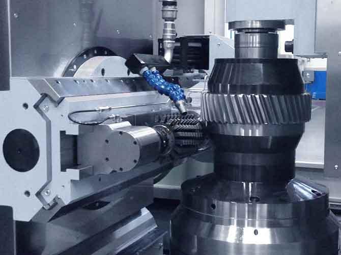
How Does the Core CNC Machining Process for a Printer Work?
This is the heart of the project. The design is sent to the CNC machine, where skilled programming and precise cutting turn it into physical parts.
Step 1: CAM Programming and Toolpath Design
Your 3D models are imported into CAM software like Mastercam. The programmer sets the machining origin and then creates the toolpaths.
| Programming Step | Key Actions |
|---|---|
| Roughing | Use large flat cutters (10-12mm) to remove 80-90% of the excess material fast. Leave a 0.5-1mm allowance for finishing. |
| Finishing | Use small ball cutters (0.5-1mm) for fine details like gear teeth and button grooves. Take very thin cuts, 0.1-0.2mm per pass. |
| Corner Cleaning | Use small end mills (2-3mm) to clean out material from tight corners, like inside a cartridge bin. |
| Parameter Setting | Adjust speed and feed for the material. For aluminum: 8000-10000 RPM. For ABS plastic: 4000-6000 RPM. |
Step 2: Clamping the Parts Securely
Holding the material correctly prevents movement and ensures accuracy.
- For aluminum blocks, use a vise with soft jaws to avoid scratching the surface.
- For thin plastic sheets (like 2-3mm ABS for housings), use a vacuum suction cup. This holds the part flat with even pressure.
- For irregular parts like gear sets, you might need a custom jig.
For symmetrical parts like upper and lower housings, use double-sided clamping. Machine one side, then flip the part and carefully re-calibrate to ensure both halves match perfectly, with an error of less than ±0.05mm.
Step 3: Machining Execution
The machine now follows the program.
- Roughing: The machine quickly shapes the basic outline of the part, like the outer edges of a housing or the main slots for the feeder.
- Finishing: This is where precision happens. The machine cuts critical features like gear teeth (keeping tooth pitch error under ±0.02mm) and mounting holes. For threaded holes (M2 to M4), it uses taps for plastic or thread mills for metal.
- Special Processing: For curved surfaces, like the edge of a paper exit tray, the machine might use 4-axis linkage to create a smooth, consistent curve.
Step 4: Quality Inspection During Machining
It is smart to check the parts as they are being made.
- Use calipers to check outer dimensions and micrometers for gear shafts (tolerance ±0.01mm).
- Use a stylus roughness meter to check surface finish. For visible parts like the housing, aim for Ra ≤ 1.6μm.
- Use go/no-go gauges to test threaded holes and slot widths, ensuring they will fit their mating parts.
What Post-Machining Steps Finish the Printer Parts?
Once machining is done, the parts need finishing touches to look good and work properly.
Deburring and Polishing
First, remove all sharp edges and burrs.
- For plastic parts, use fine 400-grit sandpaper. For metal parts, use small files—round files for holes, flat files for edges.
- Blow out any debris from small holes using compressed air at 0.5-0.8 MPa.
- For a smooth finish, you can polish parts. Aluminum parts can go in a vibration grinder for 1-2 hours. Plastic parts can be polished with a wool wheel and polishing paste.
Applying Material-Specific Surface Treatments
Different materials need different treatments to achieve the desired look and feel.
| Material | Surface Treatment Method | Purpose & Effect |
|---|---|---|
| Aluminum Alloy | Sandblasting + Anodizing | Sandblasting creates a uniform matte texture. Anodizing (5-10μm thick) adds corrosion resistance and allows for colored finishes like black or silver. |
| ABS Plastic | Painting + Silk Screen | Apply 2-3 coats of matte or gloss paint for aesthetics. Then silk screen print brand logos, button symbols (like “Power”), and warning text. |
| Acrylic | Laser Engraving | Engrave scale marks (like paper capacity) on transparent windows without harming clarity. An anti-fingerprint coating can also be applied. |
| POM Gears | Oil Coating | Apply a thin coat of food-grade silicone oil to the gear teeth. This reduces friction, quiets operation, and can extend gear life by up to 30%. |
How Do You Assemble and Test the Printer Prototype?
With all parts finished, it is time to put the printer together and see if it works.
The Assembly Process
Follow a careful sequence to avoid mistakes.
- Pre-Assembly Check: Use a coordinate measuring machine (CMM) to double-check critical dimensions, like the distance between gear centers (tolerance ±0.03mm). Test-fit parts to ensure no interference.
- Housing Assembly: Fasten the upper and lower housings with M3 screws, using a torque of about 1.5-2 N·m. Check that the seam is even with no gaps.
- Install Structural Parts: Mount the feeder and paper exit tray. Secure them with snaps or screws. Adjust the feeder rollers so paper travels straight.
- Install Moving Parts: Mount the gear sets and cartridge bins. Add lubricant to the gears. Check the gear meshing—the backlash should be under 0.05mm to prevent jamming.
- Install Electronics: Mount the circuit boards and connect the wires. Ensure sensors are aligned correctly, with a position error of less than 0.5mm.
- Final Check: Give the assembled printer a gentle shake. There should be no rattling sounds.
Testing Procedures
Now, put the prototype through its paces.
- Appearance Inspection: Check the color consistency and look for any surface scratches or defects.
- Paper Handling Test: Load the feeder with 100 sheets of standard A4 paper. Run paper through and check for jams. The paper should not skew more than 1mm.
- Gear Transmission Test: Run the gear sets at 500 RPM for one hour. After the test, inspect the gear teeth for wear (damage should be under 0.01mm). The noise level should stay below 55 decibels.
- Cartridge Compatibility: Insert and remove the ink cartridges 20 times. The action should be smooth, with no sticking.
- Functional Verification: For an electronic prototype, test the circuit board connections, sensor response times (paper detection should be under 0.1 seconds), and indicator lights.
How Do You Optimize the Prototype and Document the Results?
Testing will reveal issues. This feedback is gold for improving your design.
- Log the Problems: Record every defect. Take photos and make notes like “Housing has a 0.2mm gap at the left edge.”
- Optimize the Design: Go back to your 3D models. You might need to adjust a part’s size (e.g., increase gear tooth thickness by 0.1mm), add chamfers to reduce burrs, or simplify a snap design.
- Secondary Processing: Sometimes you can rework the existing parts. You might re-machine a hole that is too small or polish out a scratch. Replace any parts that are completely non-functional.
Finally, deliver a complete package to the client. This includes:
- The assembled functional prototype.
- All technical documents: 3D model files (STEP), 2D drawings (DXF), CNC programs (G-code), assembly drawings, and inspection reports.
- A feedback report summarizing the challenges faced and solutions found, with suggestions for mass production.
Conclusion
The professional CNC machining printer prototype process is a comprehensive journey from a digital concept to a physical, testable machine. It requires careful planning in the design stage, where you split the complex model into machinable parts and select the right materials like ABS for housings and POM for gears. The core CNC process, with its precise programming and multi-step machining, creates parts with tight tolerances, such as ±0.02mm for gear teeth. Post-processing, assembly, and rigorous testing for paper feed and gear noise then validate the design. By following this structured process, you can identify and fix issues early, de-risking the path to mass production and ensuring your final printer performs reliably.
FAQ
What materials are best for CNC machined printer prototype parts, and why?
The best material depends on the part’s job. ABS plastic is ideal for housings because it is low-cost and tough. Aluminum alloy is great for brackets and shafts where strength is needed. POM (acetal) is the top choice for gears because it has low friction and runs quietly. Acrylic is perfect for any transparent windows or displays.
Can a CNC machined printer prototype be used directly for mass production?
No, it is not designed for that. CNC machining is for creating one or a few prototypes to verify the design and function. For mass production (making thousands of units), you need to switch to processes like injection molding for plastic parts or die casting for metal parts. These methods are much faster and cheaper per unit at high volumes.
How long does it take to make a CNC machined printer prototype from design to testing?
The timeline depends on complexity. For a simple desktop printer with a plastic housing and basic gears, you can expect 10 to 14 days. For a more complex laser printer with aluminum alloy parts and many precision gears, it can take 15 to 20 days, as the machining and testing are more involved.
Discuss Your Projects with Yigu Rapid Prototyping
Are you developing a new printer and need a reliable, high-quality prototype? At Yigu Rapid Prototyping, we specialize in the professional CNC machining printer prototype process. Our team of experienced engineers understands the complexities of printer mechanisms, from precise gear trains to smooth paper handling systems. We can help you select the right materials, optimize your design for manufacturability, and build a fully functional prototype that you can test with confidence.
Contact Yigu Rapid Prototyping today to discuss your printer project. Let’s work together to bring your ideas to life, one precise part at a time.