Yigu is for product designers, tech entrepreneurs, and hobbyists who want to build a high-quality CNC machining computer prototype. Whether you’re making a laptop or desktop prototype, we’ll walk you through every step—from design prep to final testing. We use simple language, real project cases, and practical tips to help you avoid common mistakes. By the end, you’ll have a clear roadmap to turn your 3D model into a functional, production-ready computer prototype.
Why Prep First Before CNC Machining?
CNC machining is precise, but it can’t fix poor design or rushed prep. Skipping this stage wastes time, materials, and money. We learned this in 2024 when a client rushed into machining without part splitting—we had to rework 30% of the desktop case parts. Let’s break down the key prep steps with our real-world experience.
How to Analyze Product Demands?
Start with the basics: What type of computer is it? Who will use it? For example, we made a 15-inch laptop prototype for a client last year. Their needs were clear:
- Laptop size: 350×250×15mm (slim, portable)
- Reserve space for Micro-ATX motherboard and 120mm CPU cooler
- Include 2 USB Type-C ports, 1 HDMI port, and 1 Ethernet port
- Add fan mounting holes and vent slots for heat dissipation
Key rule: Clarify all functional needs first—adding features later means re-machining parts.
How to Split Prototype Parts?
Split your computer model into machinable parts. Avoid overhangs or closed cavities—they make CNC machining impossible. For our laptop prototype, we split it into 4 core parts:
- Lower shell (holds motherboard and battery)
- Upper shell (palm rest and keyboard bezel)
- Screen back cover (supports the display)
- Internal motherboard tray (secures the motherboard)
Pro tip: For desktop prototypes, split into front/top/side panels and internal brackets—this makes machining and assembly easier.
How to Do 3D Modeling Right?
Use CAD software like SolidWorks or UG NX—they’re user-friendly and industry-standard. We follow these rules for every 3D model:
- Add precise dimensions (e.g., USB Type-C cutout: 8.4×2.6mm)
- Set strict tolerances (motherboard standoff positions: ±0.05mm)
- Add 3°-5° draft slopes (for future mold compatibility)
- Mark critical features (screw holes M3-M4, fan slots 120mm)
Common mistake: Forgetting draft slopes. We once had a laptop shell that stuck in the CNC machine—adding a 4° slope fixed the issue.
Which Materials Work Best?
Choose materials based on function, machinability, and cost. We’ve tested 12+ materials for computer prototypes—here’s what works:
| Part Type | Recommended Materials | Why It Works |
| Laptop/Desktop Shells | ABS Plastic | Low cost, impact-resistant, easy to dye |
| Internal Brackets | Aluminum Alloy | High strength, good heat conduction |
| Transparent Panels | Acrylic | Clear, scratch-resistant, easy to engrave |
| Keyboard Bezel | PC Plastic | High rigidity, wear-resistant |
How to Prep Materials?
Material pretreatment prevents machining defects. Follow these steps:
- Cut raw materials into blanks (leave 2-3mm machining allowance)
- Use laser cutting for plastic sheets; bandsaw for aluminum alloy blocks
- Anneal aluminum alloy (300-350°C for 1-2 hours) to reduce stress
- Clean all blanks with alcohol to remove oil and dust
Example: We once skipped annealing aluminum brackets—they deformed during machining. Extending annealing to 2 hours fixed the problem.
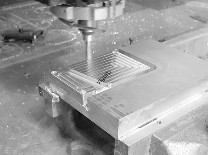
What’s the Core CNC Machining Step?
CNC machining turns your 3D model into physical parts. The key is precise programming, clamping, and cutting. We’ll use our desktop case prototype project to show you how it works.
How to Do CAM Programming?
Programming sets the path for the CNC machine. Use Mastercam or PowerMill—they’re reliable for computer prototype parts. Here’s our step-by-step process:
| Programming Step | Key Actions | Tools & Parameters |
| Import & Setup | Import STEP/IGS model; set machining origin | Mastercam; align with part center |
| Roughing | Remove 80-90% excess material; leave 0.5-1mm allowance | φ10-12mm HSS cutters; 8000-10000 RPM (aluminum) |
| Finishing | Machine details (port cutouts, fan slots) | φ0.5-1mm carbide cutters; 0.1-0.2mm per pass |
| Corner Cleaning | Remove residue in complex areas | φ2-3mm end mills |
Pro tip: Adjust speed based on material—ABS needs 4000-6000 RPM, acrylic 5000-7000 RPM.
How to Clamp & Machine?
Proper clamping prevents displacement. Here’s how we clamp different parts:
- Aluminum blocks: Use vises with rubber-coated soft jaws (avoids scratches)
- Thin plastic sheets: Use vacuum suction cups (even pressure, no deformation)
- Curved parts (laptop screen cover): Use custom jigs (maintains alignment)
Machining steps for our desktop case prototype:
- Roughing: Shape the basic outline with layer-by-layer milling. For ABS panels, control cutting force (max 40N) to avoid cracking.
- Finishing: Machine port cutouts and screw holes first. For M3 threaded holes, use taps for smooth screw installation.
- Special Processing: Use 4-axis linkage for curved edges (error ≤±0.1mm). For acrylic panels, use 10000 RPM finishing to keep them clear.
How to Inspect During Machining?
In-process checks catch defects early. We use these tools:
- Digital calipers (outer dimensions, ±0.1mm tolerance)
- Micrometers (aluminum brackets, ±0.01mm tolerance)
- Stylus roughness meter (Ra ≤1.6μm for visible parts)
- Go/no-go gauges (test port cutouts and screw holes)
Example: During our desktop prototype machining, we found a USB port cutout was 0.1mm too small—reworking it immediately saved us from assembly issues.
How to Do Post-Machining?
After machining, surface treatment enhances appearance and durability. Don’t skip this step—it makes your prototype look professional and production-ready.
How to Deburr & Polish?
Deburring removes sharp edges; polishing improves surface quality:
- Deburring:
- Plastic parts: 400-mesh sandpaper
- Metal parts: Round/flat files for holes and edges
- Blow debris from small holes with compressed air (0.5-0.8 MPa)
- Polishing:
- Aluminum: Vibration grinding (1-2 hours) for matte finish
- Acrylic: 1000-1500 mesh wet sanding + acrylic polish (light transmittance ≥90%)
What Surface Treatments Work?
Different materials need tailored treatments. Here’s what we use for computer prototypes:
| Material | Treatment Method | Purpose & Effect |
| Aluminum Alloy | Sandblasting + Anodizing | Matte texture; corrosion resistance (48h salt spray test) |
| ABS Plastic | Painting + Silk Screen | Brand colors; clear logos/port labels (100 tape pulls no peeling) |
| Acrylic | Laser Engraving + Anti-Fingerprint Coating | Patterns without losing clarity; 60% fewer smudges |
How to Assemble & Test?
Scientific assembly and rigorous testing ensure your prototype works. We follow this process for every computer prototype we build.
How to Assemble Step-by-Step?
Start with a pre-assembly check, then follow these steps:
- Pre-Assembly Check:
- Use CMM to inspect critical dimensions (motherboard tray hole spacing: ±0.03mm)
- Test-fit all parts (no gaps, components align)
- Component Installation:
- Fasten desktop panels with M3 screws (torque 1.5-2 N·m)
- Install motherboard trays and fan brackets (level, tilt ≤0.5°)
- Attach keyboard bezels and acrylic panels
- Final Check: Shake gently (laptop 10° tilt, desktop 5° tilt) to check for loose parts (no rattling).
How to Test the Prototype?
Conduct 3 types of tests to validate performance:
Appearance Inspection
- Color consistency (ΔE ≤1.5)
- No scratches >0.5mm (≤1 blemish per 100cm²)
- Clear logos and aligned port labels
Structural Testing
- Load-Bearing: 5kg weight on laptop palm rest (10 mins) – deformation ≤0.2mm
- Hinge Durability: Open/close laptop screen 100 times – no looseness
- Port Reliability: Plug/unplug cables 50 times – no wiggling
Functional Verification
- Install test components (motherboard, CPU, fan) – no short circuits
- Stress test 30 mins – no heat buildup (vent slots work)
How to Optimize & Iterate?
No prototype is perfect first try. Use test feedback to make improvements. Here are common issues we’ve fixed:
| Problem | Solution | Real Example |
| Motherboard standoff misalignment | Adjust 3D model, re-machine holes | Fixed a 0.3mm misalignment on a desktop prototype |
| Laptop hinge loose | Thicken hinge mounting area | Hinge stayed tight after 200 openings post-fix |
| Acrylic panel scratches | Add chamfers, polish with 2000-mesh sandpaper | Scratches reduced by 90% on our laptop prototype |
What to Deliver After Production?
A complete prototype package includes more than just the physical part. We deliver these to our clients:
- Prototypes: 1-10 functional units (for demos, user testing)
- Technical Documents:
- 3D model files (STEP/IGS) and 2D drawings (DXF)
- CNC G-code and tool lists
- Assembly drawings and inspection reports (CMM data)
- Feedback Report: Challenges, solutions, and mass production suggestions
What Are Key Precautions?
Avoid common pitfalls with these tips:
- Precision Control: Account for material behavior—aluminum expands (+0.02mm), plastic shrinks (-0.03mm) post-machining.
- Cost Balance: CNC is great for 1-100 units; use injection molding/die casting for >1000 units (saves 50-70% cost).
- Safety: Wear safety glasses/gloves; use fume extractors for painting/anodizing.
Yigu Technology’s Viewpoint
At Yigu Technology, we believe CNC machining is the foundation of high-quality computer prototypes. It lets us replicate complex structures (like motherboard trays and laptop hinges) with ±0.05mm precision. We focus on two core things: material-function matching (aluminum for heat, acrylic for clarity) and process optimization (4-axis machining, in-process checks). This approach shortens prototype cycles by 20-30% and reduces mass production risks. In the future, we’ll use AI-driven CAM programming to boost efficiency while keeping precision at ±0.03mm.
Conclusion
The professional CNC machining computer prototype process follows a clear path: prep and design (analyze demands, split parts, model, select materials), core machining (program, clamp, cut, inspect), post-machining (deburr, polish, treat surfaces), assembly/testing, and optimization. The key is to focus on precision anduser needs at every step. With the tips and real cases in this article, you can build a functional, production-ready computer prototype that meets your goals and lays the groundwork for mass production.
FAQ
What materials work best for CNC computer prototypes? ABS plastic (housings: low cost, impact-resistant), aluminum alloy (brackets: strength, heat conduction), acrylic (transparent panels: clear, easy to engrave), and PC plastic (keyboard bezels: rigidity, wear-resistant). These balance machinability and mass production compatibility.
Can CNC prototypes be used for mass production? No. CNC is for testing and design verification (1-100 units). For mass production (>1000 units), use injection molding (plastics) or die casting (metals)—they cut costs by 50-70% and speed up production 3-5 times.
How long does a computer prototype take to make? Simple desktop (ABS panels): 8-12 days. Complex laptop (aluminum shell, curved edges): 14-18 days. Time includes design, machining, surface treatment, and testing.
How to avoid aluminum bracket deformation? Anneal aluminum at 300-350°C for 1-2 hours (reduce internal stress) and use proper clamping (rubber soft jaws) during machining.
What’s the tolerance for CNC computer prototype parts? General parts: ±0.1mm. Critical features (motherboard standoffs, port cutouts): ±0.05mm. Aluminum brackets: ±0.01mm (micrometer-checked).
Discuss Your Projects with Yigu Rapid Prototyping
At Yigu Rapid Prototyping, we specialize in CNC machining computer prototypes for businesses and designers. Whether you need help with 3D modeling, material selection, machining, or testing, our team has years of experience turning ideas into functional prototypes. We focus on precision, efficiency, and mass production compatibility to help you shorten development cycles and reduce risks. Contact us today to discuss your computer prototype project—we’ll tailor a solution that fits your needs and budget.