In the world of mechanical engineering, transmission shafts act as the “spine” of a machine. They carry the heavy burden of moving power from engines to wheels, aircraft propellers, and industrial turbines. However, many engineers face a frustrating problem: Why do some shafts fail early or vibrate uncontrollably?
The answer almost always lies in the Transmission shaft CNC machining process design. A scientific design is more than a set of instructions; it is a guarantee of precision. A well-planned process extends service life, slashes production costs, and ensures the part performs reliably under extreme stress. This guide will walk you through the essential stages and expert strategies for mastering this critical manufacturing task.
Why Is Process Design Critical for Transmission Shafts?
Transmission shafts operate in high-stress environments, constantly fighting torque and vibration. If the CNC machining process is poorly planned, you face a nightmare of tolerance errors and high scrap rates.
Comparing Process Design Quality
The table below highlights how much a professional process design impacts the final product:
| Aspect | Poor CNC Process Design | Excellent CNC Process Design |
| Dimensional Precision | Low (errors often > 0.05mm) | High (Level 6 or 7 tolerance) |
| Service Life | Short (6 – 12 months) | Long (2 – 3 years) |
| Production Cost | High (Rework rate > 20%) | Low (Rework rate < 3%) |
| Assembly Fit | Poor (Requires manual sanding) | Perfect (Direct “Drop-in” assembly) |
Real-World Case: A major auto parts plant struggled with an 18% failure rate on their shafts due to loud abnormal noises during testing. The cause was poor coaxiality. After we redesigned their CNC sequence—specifically reordering the turning, heat treatment, and finishing stages—the coaxiality error vanished, and their failure rate plummeted to just 2%.
What Are the Core Stages of the CNC Design Process?
Designing the machining flow for a transmission shaft is a linear, 8-stage project. Think of it as a chain; the final product is only as strong as its weakest link.
1. Drawing and Blueprint Creation
Everything starts with CAD software. You must create a “digital twin” of the shaft. This blueprint must specify the diameter and length of every section, the exact tolerance levels, and surface roughness standards (like Ra1.6 for bearing seats).
2. Strategic Material Selection
You must match the metal to the load.
- Carbon Steel: Used for general, light-duty loads.
- Alloy Steel: Essential for high-torque industrial machinery.
- Stainless Steel: The best choice for marine or corrosive environments.Once selected, the material is cut and grooved into a “blank” ready for the machines.
3. Electrode and Initial Shaping
Using a CNC machine, we process electrodes for electrical discharge machining (EDM). This step “carves” the preliminary shape and ensures the surface is flat and ready for the complex work ahead.
4. Engraving and Etching
Modern shafts require traceability. We use professional engraving tools to add part numbers and production dates. We also machine notches and holes at this stage to help workers align the shaft correctly during the final assembly.
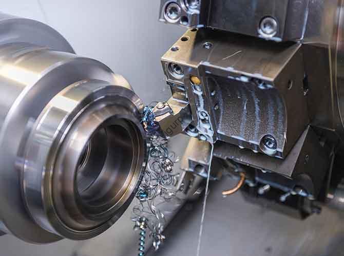
5. Precision Turning and Punching
This is where the shaft takes its final form. We use CNC lathes to ensure the outer diameter is perfectly round. Simultaneously, CNC milling machines punch holes at specific positions. This stage is the heartbeat of dimensional precision.
6. Heat Treatment and Strength
Before the final “beauty” pass, the shaft undergoes quenching and tempering. Heat treatment changes the molecular structure of the steel, making the shaft much harder and resistant to the “twisting” force of torque.
7. The Finishing Pass
Finishing is like polishing a diamond. We perform semi-finishing and finishing on the circular surfaces and U-grooves. This step removes the tiny imperfections left by earlier stages and brings the part into its final, tight tolerance range.
8. Tapping and Threading
Finally, we drill and tap holes, such as M8 threaded holes. these allow the shaft to connect securely to flanges or couplings, ensuring that power flows smoothly without slipping.
What Factors Determine a Reliable Process Design?
Following the steps is not enough. To reach professional standards, you must focus on three technical pillars.
How Strict Are the Tolerance Requirements?
Different sections of the same shaft need different levels of care. For example, a Ф60 section often requires a Level 6 tolerance. This means the error cannot be more than a few thousandths of a millimeter.
- Too Loose: Power is lost through vibration.
- Too Tight: Friction increases, causing the bearing to overheat and fail.
Why Is Coaxiality the “Golden Rule”?
Coaxiality measures how well the centers of different shaft sections align on a single straight line. If the coaxiality is off, the shaft behaves like a bent stick. As it rotates at high speeds, it swings, creates noise, and eventually destroys the bearings.
Why Does Surface Roughness Matter?
We aim for a roughness of Ra1.6 on key surfaces. A smooth surface reduces the “drag” between the shaft and its housing. It also prevents dirt from sticking to the metal, which keeps the entire transmission system cleaner and more reliable over thousands of hours of use.
Yigu Technology’s View on Machining Design
At Yigu Technology, we believe that the design of the machining process is the single biggest factor in product competitiveness. Our engineers don’t just follow drawings; we optimize them. By integrating advanced CNC programming and AI-driven error prediction, we have helped our clients reduce material waste by 15% to 20%.
We have found that by carefully balancing the timing of heat treatment with finishing, we can extend a shaft’s life by over 50%. In the future, we plan to use even more intelligent sensors to monitor the tool’s health during the machining of high-torque alloy steels, ensuring every part we ship is a “masterpiece of precision.”
FAQ: Common Questions About Shaft Machining
Which materials work best for high-torque shafts?
Alloy steel is the gold standard. It offers much higher toughness than standard carbon steel. This allows it to absorb the sudden “shocks” of high-torque starts without snapping or deforming.
Can I do the finishing pass before the heat treatment?
No. Heat treatment involves extreme temperatures that can cause the metal to expand or warp slightly. If you finish the part first, the heat treatment will ruin your perfect dimensions. You must rough-cut, heat treat, and then perform the final finishing.
How do I check if my shaft’s coaxiality is correct?
The most accurate way is to use a coaxiality detector or a Coordinate Measuring Machine (CMM). You rotate the shaft while sensors measure the deviation from the center line. If it’s outside the design tolerance, it must be re-machined or scrapped.
What is the most common cause of abnormal noise in a new shaft?
Usually, it is a combination of poor surface roughness and coaxiality errors. If the surface is too rough, it grinds against the bearing; if the coaxiality is off, it vibrates against the housing.
Discuss Your Projects with Yigu Rapid Prototyping
Are you looking for a partner who understands the “spine” of your machinery? At Yigu Technology, we specialize in the high-precision Transmission shaft CNC machining process design. Our R&D team is ready to help you optimize your sequence, choose the best materials, and ensure your components last for years, not months.
Would you like us to review your CAD designs for a free DFM (Design for Manufacturability) analysis? Let’s build something reliable together.