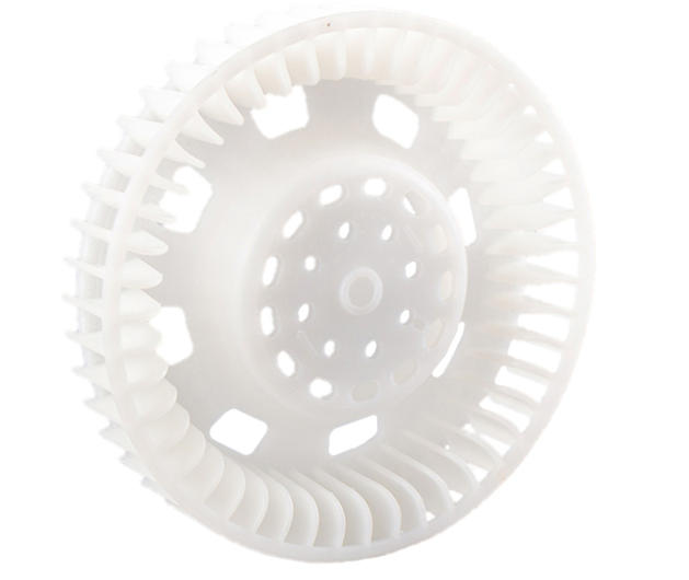
When you are developing a new automotive component, a complex electronic housing, or a specialized medical device, the porous prototype model is often the biggest hurdle. A “porous” model in this context refers to parts with a high density of holes—whether they are for ventilation, weight reduction, or complex mounting points.
Processing these models using CNC machining is a critical link in the product lifecycle. If you get it right, you ensure perfect assembly and save weeks of verification time. If you get it wrong, you face material waste, broken tools, and misaligned components. This guide provides a deep dive into mastering the CNC machining of porous prototypes, offering professional solutions to keep your projects on track.
Why Is Design the Foundation of Precision?
The first step to process porous prototype models in CNC is not on the factory floor, but at the computer. Your digital strategy directly dictates the final accuracy of every hole position.
3D Modeling with CAD
Using professional software like SolidWorks or AutoCAD, you must create a “scientific” design. This means looking beyond just where the holes go. You must analyze the hole spacing, the thickness of the walls between holes, and how these cavities interact with the internal structure.
Advanced CAM Programming
Once the 3D model is ready, you move to CAM software like Mastercam or UG. This is where you define the “DNA” of the machining process:
- Coordinates: Every hole needs a precise X, Y, and Z origin.
- Depth Control: You must distinguish between through-holes (e.g., 5mm) and blind holes (e.g., 3mm) to prevent tool crashes.
- Machining Sequence: A pro tip is to work from the edge to the center. This prevents the part from warping as material is removed.
Real-World Case: We recently processed a porous aluminum alloy enclosure. The design had 20 M3 threaded holes with tight 15mm spacing. By programming the CNC to start at the four corners before moving to the center, we balanced the internal stress. This kept the flat surface from “bowing,” a common failure when machining many holes in a small area.
How to Match Materials and Tools for Success?
Selecting the right “partner” for your material is non-negotiable. If you use a plastic-grade drill on stainless steel, the tool will melt or snap in seconds.
Material Selection Guide
| Material Type | Core Advantages | Best Use Case | Difficulty |
| ABS Plastic | Low cost, very light | Enclosures, air-flow mocks | Low |
| PC Plastic | Impact & heat resistant | Automotive interior panels | Medium |
| Aluminum 6061 | Rigid, high heat transfer | High-precision structural parts | Low |
| Stainless 304 | High strength, anti-rust | Medical surgical prototypes | High |
Tool Selection Logic
- For Plastics (ABS, PC): Use High-Speed Steel (HSS) drills. A secret of the trade is to choose a drill bit 0.1mm smaller than the target diameter. Why? Plastics expand slightly when they get warm during cutting; this “undersizing” compensates for that expansion.
- For Metals (Aluminum, Steel): You need Carbide drills. They stay sharp much longer. For stainless steel, choose a drill with a 30° to 40° spiral angle. This steep angle acts like a screw to pull tough metal chips out of the hole quickly.
Is Your Setup Stable Enough for Micro-Accuracy?
Even the best program fails if the material moves. When you have dozens of holes, a shift of just 0.05mm at the start can turn the final hole into scrap.
Rock-Solid Fixing
Place your material on the workbench and use a vise or pressure plates.
- The Backing Plate Trick: If your material is thinner than 3mm, always place a sacrificial backing plate (like MDF or a plastic sheet) underneath. This lets the drill pierce the part completely without hitting the expensive metal workbench.
- Verification: Use a dial indicator to sweep the surface. The “runout” (wobble) must be under 0.02mm.
Tool Installation Check
When you load your drill into the spindle, use a tool setting gauge. This calibrates the length to ensure your blind holes are never too deep.
Safety Step: Run the spindle at a low 500 RPM for 10 seconds. Watch the tip; if you see any “blur” or eccentricity, the tool is not centered and will produce oval-shaped holes.
How to Monitor the Process in Real-Time?
During the CNC machining of a porous prototype, you must be an active observer. Parameters often need “on-the-fly” tweaks based on the sound and look of the cut.
Key Monitoring Metrics
- Spindle Speed: For aluminum, stay between 4000-6000 RPM. If you go too high (8000+), the tool wears out instantly. For stainless steel, drop it to 1500-3000 RPM to manage the heat.
- Feed Rate: Plastics can handle a fast 100-200 mm/min. Metals need a more careful 50-150 mm/min.
- Chip Shape: This is the best “health check” for your process.
- Continuous Ribbons: Perfect. The tool is cutting cleanly.
- Small Crumb-like Pieces: The feed is too fast or the tool is dull. Reduce the feed rate by 20% immediately.
Final Steps: Quality Control and Finishing
After the machine stops, the prototype is roughly 90% complete. The final 10% determines if it is a professional model or just a piece of junk.
The Inspection Checklist
- Visual Check: Look for “burrs” (small flaps of metal) or heat cracks around the hole entrance.
- Dimensional Accuracy: Use a digital caliper for the diameter. The tolerance should be within ±0.05mm.
- Positioning Accuracy: For high-end parts, use a Coordinate Measuring Machine (CMM). This ensures the distance between the first and last hole hasn’t drifted by more than 0.03mm.
Professional Post-Processing
- Deburring: Use a 400-grit sandpaper or a rotary deburring tool. This is vital for threaded holes; a single burr can stop a screw from ever going in.
- Cleaning: Wipe the surface with isopropyl alcohol to remove oily cutting fluids and dust.
- Surface Treatment: For aluminum, we recommend anodizing; for steel, use passivation. This adds a layer of protection that makes the prototype look like a finished product.
Yigu Technology’s View on Porous Prototypes
At Yigu Technology, we believe that processing porous prototype models in CNC is a mix of high-tech software and “old-school” shop floor experience. We have seen many clients fail because they ignored basic tool calibration or used the wrong fixing method.
Our approach uses CNC simulation software to “dry run” every program. This identifies potential collisions before a single chip is cut, reducing errors by 30%. Furthermore, our custom carbide tools are designed specifically for the high-repetition nature of porous parts, extending tool life by 40%. We don’t just make holes; we deliver engineering certainty.
FAQ: Frequently Asked Questions
What should I do if the hole positions are consistently off?
First, check your fixtures. If the material is vibrating, the holes will drift. Next, re-calibrate your tool length and radius with a setting gauge. Finally, check your CAM code—sometimes a simple coordinate error in the software is the culprit.
Can I use one drill bit for different hole sizes?
No. Using a smaller bit to “circle out” a larger hole (interpolating) is possible, but for the best accuracy and speed in a porous prototype, you should use a drill bit that matches each specific diameter.
How do I prevent drills from snapping in deep holes?
Use the “Peck Drilling” method. Program the CNC to drill 3-5mm, then fully retract the tool to clear out the chips before going deeper. Also, increase your coolant flow to keep the tip from softening due to heat.
Which material is best for a “see-through” porous prototype?
PC (Polycarbonate) is the best choice. It is transparent and much stronger than acrylic, making it ideal for prototypes where you need to see internal fluid flow or light.
Is CNC better than 3D printing for porous parts?
For functional testing, yes. CNC-machined holes have much smoother internal walls and better “roundness” than 3D-printed holes, which often suffer from “stair-stepping” layers.
Discuss Your Projects with Yigu Rapid Prototyping
Are you struggling with a complex, multi-hole design? At Yigu Technology, we specialize in the CNC machining of porous prototype models. Our expert engineers will analyze your CAD files, suggest the best material-tool combinations, and ensure your prototype arrives on time and within spec.
Would you like a free DfM (Design for Manufacturability) report for your porous design? Contact us today, and let’s turn your blueprints into reality.