Introduction
Have you ever looked at a complex metal part—like an engine block, a surgical tool, or the case of your smartphone—and wondered how it was made? Chances are, process milling played a key role. Milling is a subtractive manufacturing technique that uses rotating cutting tools to remove material from a solid workpiece. It can create everything from simple flat surfaces to complex 3D shapes with incredible precision. This versatility makes it one of the most important processes in industries ranging from automotive and aerospace to medical devices and electronics. In this guide, we will explore what process milling is, how it works, the different types of machines and operations, and how to get the best results for your projects.
What Exactly Is Process Milling and Why Does It Matter?
At its simplest, process milling is a way to shape raw materials like metal, plastic, or wood by cutting away unwanted material. A spinning tool with sharp edges moves across the workpiece, shearing off chips until the desired shape remains. Unlike turning, where the workpiece spins, milling keeps the workpiece stationary (or moving slowly) while the tool does the work.
The Key Elements of Milling
Every milling operation involves four main components:
- The workpiece: The raw material you start with—a block of aluminum, a sheet of plastic, or a piece of steel.
- The cutting tool: Usually an endmill, face mill, or drill bit with sharp edges that spin at high speed.
- The milling machine: The equipment that holds the workpiece and moves the tool (or moves the workpiece under the tool).
- Cutting parameters: The settings you choose—spindle speed, feed rate, and depth of cut—that determine how fast and how accurately material is removed.
Why Milling Is Indispensable
Milling matters because it offers a unique combination of versatility, precision, and efficiency.
- Versatility: It works on almost any material, from soft plastics to hard titanium. You can make flat surfaces, slots, threads, gears, and complex 3D contours all on the same machine.
- Precision: Modern CNC mills can hold tolerances as tight as ±0.0001 inches. That level of accuracy is critical for parts like aerospace components, where a tiny error can cause failure.
- Efficiency: Once programmed, a CNC mill can run unattended, producing hundreds or thousands of identical parts with consistent quality.
Real-World Example: In the automotive industry, transmission housings are made by milling. A raw aluminum block goes into a CNC machine, which carves out internal chambers for gears, drills bolt holes, and smooths the outer surfaces. Without milling, creating these complex, precise parts would be slow, expensive, and error-prone.
What Key Factors Influence Milling Success?
Getting good results from milling is not automatic. You have to understand and control several critical factors.
Material Properties: The Foundation
The material you are cutting drives every other decision. Hard materials need tougher tools and slower speeds. Soft materials need sharp tools and careful heat management.
| Material Type | Examples | Milling Considerations |
|---|---|---|
| Metals | Steel, aluminum, brass, titanium | Steel: Use HSS or carbide tools; slower speeds. Aluminum: Faster speeds; carbide for precision. Titanium: Very hard; use carbide with coolant. |
| Plastics | Acrylic, nylon, polyethylene | Soft plastics: Sharp tools, lower feed rates to avoid melting. Rigid plastics: Faster speeds, but watch for cracking from heat. |
| Wood | Pine, oak, maple | HSS tools work fine. Use fine teeth and cut with the grain to avoid tear-out. |
Professional Tip: Look up the material’s “machinability rating” before you start. A low rating means you need to adjust speeds and feeds accordingly.
Cutting Tool Selection: Choose Wisely
The tool is the heart of the milling process. Pick the wrong one and you will get poor finishes, broken tools, or ruined parts.
- Tool Material:
- High-Speed Steel (HSS): Affordable, good for soft materials like wood, aluminum, and low-carbon steel.
- Carbide: Harder, heat-resistant. Essential for titanium, stainless steel, and high-volume production. Costs more but lasts longer.
- Ceramic: Even harder, used for ultra-hard materials. Brittle, so handle with care.
- Tool Geometry:
- End Mills: For slots, pockets, and contours. 2-flute tools work well for aluminum; 4-flute for steel.
- Face Mills: Flat, disc-shaped tools for creating smooth, flat surfaces.
- Ball Nose End Mills: Rounded tips for 3D contours and curved surfaces.
Case Study: An aerospace manufacturer was milling titanium turbine blades with HSS tools. The tools wore out after just 5 parts. Switching to carbide tools with a titanium nitride coating reduced tool wear by 80 percent. They could now make 40 blades per tool, saving significant time and money.
Cutting Speed and Feed Rate: Balancing Act
Cutting speed (how fast the tool spins) and feed rate (how fast the tool moves through the material) work together. Get them wrong and you face:
- Too fast: Tool overheats, poor surface finish, broken tools.
- Too slow: Wasted time, rubbing that damages the workpiece.
Here are general guidelines for common combinations:
| Material | Tool Type | Cutting Speed (SFM) | Feed Rate (IPM) |
|---|---|---|---|
| Aluminum | Carbide end mill (4-flute) | 1000–2000 | 50–200 |
| Steel (1018) | HSS end mill (4-flute) | 100–200 | 10–50 |
| Titanium | Carbide end mill (4-flute) | 50–150 | 5–20 |
| Acrylic | HSS end mill (2-flute) | 300–500 | 20–80 |
Pro Insight: Use a speed and feed calculator app. It takes the guesswork out by factoring in tool diameter, material, and depth of cut.
What Are the Two Fundamental Milling Processes?
Nearly all milling operations fall into one of two categories: face milling and peripheral milling. Understanding the difference helps you choose the right approach.
Face Milling: For Flat Surfaces
Face milling creates smooth, flat surfaces. A disc-shaped face mill with multiple teeth spins and moves across the workpiece, removing material in wide passes.
- Characteristics: High material removal rate, excellent surface finish.
- Best for: Large flat areas, reference surfaces, finishing the tops of parts.
- Real-world example: A furniture maker uses face milling to smooth the tops of oak table blanks. The process removes unevenness, creating a flat surface ready for sanding.
Peripheral Milling: For Slots and Contours
Peripheral milling uses the sides of an end mill to cut slots, pockets, grooves, and complex shapes.
- Characteristics: More precise for details, moderate material removal rate.
- Best for: Slots for bolts, gear teeth, curved edges, intricate 3D shapes.
- Real-world example: A medical device company uses peripheral milling to cut slots in a surgical bone plate. The precision ensures the slots align perfectly with the screws that will attach the plate to a patient’s bone.
Face Milling vs. Peripheral Milling: Quick Comparison
| Feature | Face Milling | Peripheral Milling |
|---|---|---|
| Tool Engagement | Entire face of the tool | Only the sides of the tool |
| Primary Use | Flat surfaces | Slots, pockets, contours |
| Material Removal | High | Moderate |
| Surface Finish | Excellent | Varies with tool and feed |
| Tool Type | Face mill | End mill |
What Types of Milling Machines Are Available?
The machine you use matters as much as the tool and material. Here are the main types.
Vertical Milling Machine (VMC)
The most common type, especially in small shops. The tool spins on a vertical axis.
- Pros: Versatile, good visibility, compact.
- Best for: General machining, prototyping, 3D shaping.
- Example: A drone startup uses a VMC to prototype aluminum propeller housings. They can watch the cut and adjust quickly.
Horizontal Milling Machine (HMC)
The tool spins on a horizontal axis. Often has a pallet changer for loading new parts while the machine runs.
- Pros: Handles large parts, long cuts, high productivity.
- Best for: Aerospace parts, automotive transmission cases, heavy equipment.
Bed Mills
The workpiece sits on a fixed bed while the tool moves. Large and rigid.
- Pros: Very stable, handles heavy workpieces.
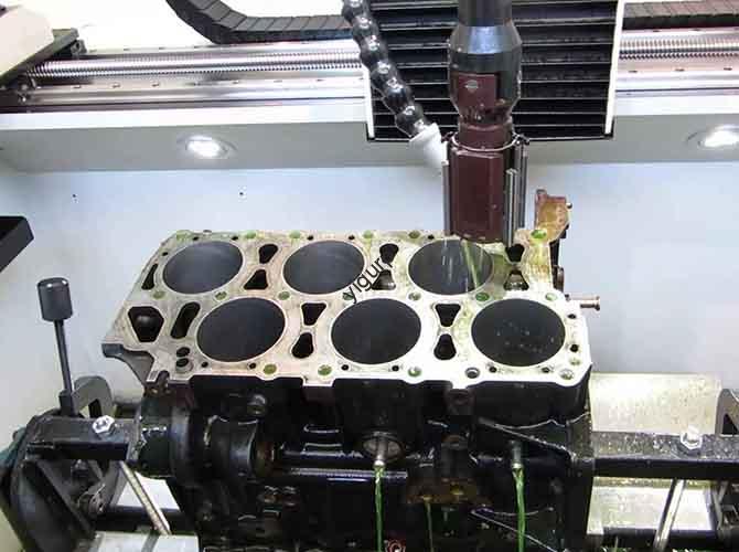
- Best for: Power generation components, large valves, engine blocks for ships.
CNC Milling Machines
Computer-controlled machines that follow digital instructions. The most advanced type.
- Pros: Extreme precision (down to ±0.0001 inches), perfect consistency, runs 24/7, easily adapts to new designs.
- Best for: Medical implants, smartphone cases, aerospace components.
- Key stat: Over 75 percent of precision machining operations in North America now use CNC mills, up from 50 percent in 2010.
What Advanced Milling Techniques Should You Know?
For complex or ultra-precise parts, basic milling may not be enough. These advanced methods push the boundaries.
3-Axis vs. 5-Axis Milling
- 3-axis moves the tool left-right, front-back, and up-down. Good for simple to moderately complex parts.
- 5-axis adds two rotational axes, letting the tool tilt and turn. Handles highly complex shapes in one setup.
Real-world example: An aerospace company switched from 3-axis to 5-axis milling for turbine blades. Production time dropped by 40 percent, and precision improved by 25 percent.
High-Speed Milling (HSM)
Uses very high cutting speeds and feed rates. The tool removes smaller chips, reducing heat and extending tool life.
- Benefits: 30 to 60 percent faster production, better surface finish, longer tool life.
- Best for: Mold making, automotive prototyping, electronics.
Micro-Milling
Creates extremely small parts with features as tiny as 0.001 inches.
- Benefits: Achieves tolerances down to ±0.00005 inches.
- Best for: Medical devices like pacemaker components, micro-needle arrays, tiny sensors.
Case study: A medical company needed a patch with hundreds of micro-needles for painless vaccine delivery. Micro-milling machined each 0.005-inch needle with precise sharpness—something traditional milling could not do.
Conclusion
Process milling is a cornerstone of modern manufacturing. It transforms raw materials into precise, functional parts for nearly every industry. By understanding the fundamentals—material properties, tool selection, cutting parameters, and machine types—you can achieve consistent, high-quality results. Whether you are milling a simple bracket or a complex aerospace component, the principles are the same. And as technology advances with 5-axis machines, high-speed techniques, and micro-milling, the possibilities only grow. Mastering process milling gives you the power to turn ideas into reality.
FAQ About Process Milling
1. What is the difference between milling and turning?
Milling uses a rotating cutting tool and a stationary (or moving) workpiece. It creates complex shapes like slots and contours. Turning spins the workpiece while a stationary tool cuts it. Turning is best for cylindrical parts like shafts and bolts.
2. Can process milling be used on non-metallic materials?
Yes. Milling works on plastics, wood, composites, and even ceramics. The key is using the right tool and adjusting speeds to avoid melting or cracking.
3. How much does a milling machine cost?
Costs vary widely:
- Manual vertical mill: (5,000 to )20,000
- CNC vertical mill: (20,000 to )100,000
- CNC horizontal mill: (100,000 to )500,000+
- 5-axis CNC mill: (200,000 to )1,000,000+
4. How long does it take to learn milling?
Basic manual milling takes 1 to 3 months with hands-on training. CNC milling, including programming, takes 6 to 12 months of practice. Advanced techniques like 5-axis or micro-milling take longer.
5. What is the future of process milling?
The future includes more automation, AI for real-time optimization, and sustainable practices like dry milling and using recycled materials.
Discuss Your Projects with Yigu Rapid Prototyping
At Yigu Rapid Prototyping, we have deep expertise in process milling across a wide range of industries. Our shop is equipped with modern CNC mills, including 3-axis and 5-axis machines, to handle everything from simple prototypes to complex production runs. We work closely with clients to select the right materials, tools, and parameters for each job. Every part goes through rigorous in-house quality control to ensure it meets your specifications. Whether you need a single component or thousands, we deliver precision and reliability. Contact Yigu today to discuss your project and get a free quote.