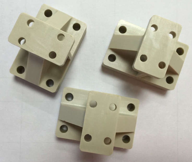
Introduction
In the fast-paced electronics industry, getting a new product from design to mass production requires careful testing at every stage. PC material electronic prototypes are the backbone of this validation phase. They let you check for design flaws, test functionality under real conditions, and cut down on development time and costs before committing to expensive production tooling. For example, a smartphone manufacturer once used PC prototypes to fix a screen frame alignment issue early, saving $50,000 in mold rework costs that would have been required if the error had reached production. This guide provides a step-by-step breakdown of how to make these high-quality prototypes, with real-world insights and practical data to help you make informed decisions.
Why Is PC Plastic the Top Choice for Electronic Prototypes?
Choosing the right material is the first critical step in prototype development. PC plastic (Polycarbonate) is the top choice for electronic prototypes, and understanding why helps you make better decisions for your specific application.
Key Properties That Make PC Ideal
Impact resistance: PC can withstand 65 kJ/m² of force (tested per ASTM D256)—about 3-4 times higher than standard ABS. This means PC prototypes survive drops and impacts during testing, giving you reliable data on durability.
Transparency: With 88% light transmission, PC offers excellent clarity for displays, light guides, and indicator windows. It is not quite as clear as glass or acrylic, but it is much tougher.
Heat resistance: PC maintains its properties at continuous use temperatures up to 120°C, making it suitable for electronics that generate heat or operate in warm environments.
Processability: PC cuts, drills, and finishes beautifully on CNC machines. It produces clean edges and holds tight tolerances without cracking or melting—critical for precision electronic components.
Comparing PC with Other Prototype Materials
| Material | Main Advantages | Ideal Prototype Uses | Trade-offs |
|---|---|---|---|
| PC Plastic | High strength, transparency, heat resistance | Phone cases, laptop bezels, sensor housings, display covers | Higher cost than ABS |
| ABS | Low cost, good rigidity, easy to paint | Remote control bodies, charger casings, internal brackets | Lower impact strength, opaque |
| PMMA (Acrylic) | Superior transparency (92% light transmission) | Display covers, light guides, decorative panels | Brittle, cracks under impact |
| PU (Polyurethane) | Flexibility, shock absorption, soft-touch feel | Smartwatch straps, protective bumpers, grips | Not rigid, limited dimensional stability |
Real Case: Fitness Tracker Prototype
A wearable tech company needed a prototype for a new fitness tracker. They compared ABS and PC options:
- ABS prototype: Cost 30% less to machine, but failed drop tests—the housing cracked after 3 drops from 1 meter.
- PC prototype: Cost more, but survived 15 drops without damage. The impact resistance was critical for a device worn during active use.
They chose PC, and the prototype data gave them confidence to move forward. The extra material cost saved them from warranty claims that would have been far more expensive.
What Data Collection Ensures Prototype Accuracy?
Without accurate data, even the best materials will fail to produce useful prototypes. This step ensures your final part matches the original design exactly.
Importing and Verifying 3D Design Files
The process starts with your 3D CAD files—typically in STEP, IGES, or native CAD formats. These files are the master blueprint. The prototyping team imports them into CAM software to plan tool paths and cutting strategies.
What your files must include:
- Exact dimensions for every feature
- Tolerances for critical mating surfaces
- Hole sizes and locations with specified fits
- Wall thicknesses throughout the part
- Surface finish requirements for visible areas
Example: A tablet maker shared SolidWorks CAD files with their prototype shop. They specified that the camera cutout needed ±0.1 mm tolerance to ensure the lens would fit perfectly. The CAM software used this data to program precision tool paths that achieved ±0.05 mm—well within requirements.
Creating Gypsum Samples for Verification
Before machining expensive PC material, smart prototyping shops create gypsum samples—cheap plaster models that verify shape, curvature, and dimensions. Gypsum is easy and fast to machine, making it ideal for this “test run.”
What gypsum samples catch:
- Shape errors not visible in CAD
- Curvature inconsistencies
- Assembly interference issues
- Aesthetic problems with complex surfaces
Case study: An automotive electronics team created a gypsum sample for a new dashboard control panel. The sample revealed that a PCB mounting slot was 2 mm too narrow—a mistake that would have made the prototype unusable. Fixing the CAD file before machining PC saved 8 hours of rework and prevented scrapping expensive material.
How Does CNC Machining Shape PC Electronic Prototypes?
CNC machining is where the design comes to life. It delivers the precision and surface quality that electronic products demand.
CNC Machining Workflow for PC
Programming and setup: Engineers write G-code that guides the CNC machine through every cut. The PC plastic sheet—typically 2–10 mm thick depending on part requirements—is clamped securely. The machine then removes excess material along programmed paths.
Precision capabilities: Modern CNC machining achieves tolerances as tight as ±0.02 mm—essential for electronic components where parts must fit precisely.
Example: For a wireless earbud prototype, the CNC program was set to carve tiny speaker grilles with 0.5 mm diameter holes. This level of detail is impossible with manual methods and critical for acoustic performance. The machine held position within ±0.01 mm, ensuring all holes were perfectly round and correctly spaced.
Multi-Axis Machining for Complex Parts
For complex electronic components—like curved smartphone cases or VR headset shells—5-axis CNC machines are essential. These machines can tilt the cutting tool to reach all sides of the part in a single setup.
Advantages of 5-axis machining:
- Reduced setup time: Eliminates multiple setups, cutting production time by 30% compared to 3-axis machines
- Improved accuracy: No errors from repositioning parts
- Complex geometries: Can create undercuts and curved surfaces impossible on simpler machines
Real result: A drone company used 5-axis machining to make PC propeller guards. Production time dropped from 8 hours to 3 hours per set, and the curved surfaces were perfectly smooth—improving aerodynamics for flight testing.
What Post-Processing Steps Perfect PC Prototypes?
Raw machined PC parts need finishing work to look and perform like final products.
Essential Post-Processing Techniques
Deburring: Machining leaves tiny tool marks and sharp edges. Technicians use 800–1200 grit sandpaper or specialized tools to smooth every surface. This is especially important for parts like USB ports—rough edges could damage cables during testing or scratch users’ devices.
Surface treatment options:
- Painting: Adds color and protects the surface. A smart speaker prototype received matte black paint to match the final product’s aesthetic. The painted surface also resisted fingerprints during user testing.
- Screen printing: Adds labels, logos, or button icons directly onto the PC surface. A headphone brand screen-printed “Power” and “Volume” labels on their PC prototype—the ink survived 500+ rub tests with cleaning solutions.
- Electroplating: A thin chrome or nickel layer can be added for scratch resistance or conductivity. A remote control prototype received a chrome finish that boosted scratch resistance and gave it a premium look for market testing.
How Do You Test PC Electronic Prototypes?
No prototype is ready until it passes thorough assembly and functional tests.
Test Assembly Inspection
All parts—PC housing, circuit boards, displays, buttons—are assembled together. Engineers check:
- Fit: Do all parts align correctly? A laptop prototype team found that the PC keyboard tray didn’t align with the body—a 0.3 mm shift that would have made typing uncomfortable. They adjusted the CNC program to fix it before production.
- Clearance: Is there enough space for components and cables?
- Fastener engagement: Do screws, clips, or other fasteners work correctly?
Functional Testing
Tests simulate real-world use to verify performance:
- Structural stability: Drop tests from 1.5 meters onto concrete. A good PC prototype survives 10+ drops without cracking.
- Mechanical performance: For moving parts like laptop hinges or folding mechanisms, cycle tests of 1,000+ openings verify no wear or loosening.
- Environmental simulation: Exposure to 60°C and 90% humidity for 48 hours checks for deformation, warping, or material degradation.
Case study: A PC battery case prototype underwent environmental testing at elevated temperatures. After 48 hours at 60°C, the case showed no warping and all internal components still fit perfectly—validating the design for use in warm environments.
How Are PC Prototypes Packaged and Shipped?
Safe delivery ensures your prototype arrives in perfect condition, ready for testing or presentation.
Packaging Best Practices
Protective materials: Prototypes are wrapped in bubble wrap and placed in custom foam inserts that prevent movement during shipping. For sensitive electronic components, anti-static packaging prevents electrostatic damage.
Documentation: Include a packing list identifying all parts and any special handling instructions. For complex assemblies, include assembly notes or photographs.
Delivery Timeline
Most PC electronic prototypes ship within 3–7 business days of completing testing:
- Simple parts (like small sensor housings): 3 days
- Complex parts (like curved VR shells): 5–7 days
- Urgent projects (like trade show demos): Expedited service can deliver in 1–2 days
Example: An IoT company needed a PC sensor prototype for their CES booth. They used expedited service—the prototype was designed, machined, finished, and shipped in 2 days, arriving just in time for the show.
What Real Problems Does PC Prototyping Solve?
Here are three cases showing how proper PC prototyping prevented major issues.
Case 1: The Phone Case That Blocked the Camera
A smartphone accessory company designed a new protective case. Their first PC prototype looked perfect, but when assembled with a test phone, the camera cutout was 0.3 mm too small—it blocked part of the lens. The error was invisible in CAD but obvious in the physical prototype. They adjusted the design, machined a new prototype, and verified the fix. Catching this early saved $15,000 in production mold modifications.
Case 2: The Smart Speaker That Rattled
A consumer electronics company tested a PC prototype for a new smart speaker. During acoustic testing, they noticed a rattle at certain frequencies. Investigation traced the issue to a slightly loose internal bracket mount. They added 0.2 mm of material to the mounting boss in the CAD model, machined a new prototype, and the rattle disappeared. Fixing this before production prevented thousands of customer complaints.
Case 3: The Wearable That Overheated
A fitness tracker company tested a PC prototype in warm conditions—35°C ambient temperature. The device overheated, with internal temperatures reaching 55°C—above safe limits for skin contact. Analysis showed the PC housing trapped too much heat. They added ventilation slots to the design, machined a new prototype, and retested. Internal temperatures dropped to 42°C, within safe limits. The design change cost nothing in production but prevented a safety recall.
Yigu Technology’s Perspective on PC Electronic Prototypes
At Yigu Technology, we have supported over 500 electronics companies with PC prototype manufacturing over the years. We believe the key to a great prototype is balancing precision and speed.
Our 5-axis CNC machines achieve the tight tolerances that electronics demand—typically ±0.02 mm on critical features. Our experienced post-treatment team ensures every prototype looks and feels like a production part.
We often recommend PC plastic for clients who prioritize durability and transparency. For a smart home company developing new light switches, PC prototypes let them test both the look (transparent covers for LED indicators) and the feel (impact resistance for daily use) before committing to production.
We tailor our process to each client’s timeline—whether it is a 3-day rush order for a trade show demo or a detailed 2-week project requiring multiple iterations and extensive testing.
For clients, this means faster design validation and fewer surprises when moving to production. We do not just make parts—we help you build confidence in your product.
Conclusion
The process of creating electronic product prototype models from PC materials transforms digital designs into physical devices you can test, validate, and refine. Starting with careful material selection—PC for its unique combination of impact resistance, clarity, and heat tolerance—and progressing through precise CNC machining, thorough post-processing, and rigorous testing, each step builds confidence that your final product will perform as intended. Real cases show that companies investing time in proper PC prototyping avoid expensive field failures, accelerate development, and create electronics that meet demanding real-world requirements.
FAQ
Why is PC plastic better than ABS for electronic prototypes?
PC plastic has significantly higher impact resistance (65 kJ/m² vs. 15–20 kJ/m² for ABS) and better heat resistance (continuous use up to 120°C vs. 80°C). This makes PC ideal for parts that need to withstand drops, heat, or wear during testing. PC also offers 88% light transmission for display-based devices, while ABS is opaque. The trade-off is cost—PC is typically 20-30% more expensive than ABS.
How long does it take to make a PC electronic prototype?
Typical lead time is 3–7 business days from file approval to shipping. Simple parts like small sensor housings can ship in 3 days. Complex parts with curved surfaces or tight tolerances—like VR headset shells—require 5–7 days. For urgent projects, expedited service can deliver in 1–2 days.
Can PC prototypes be used for user testing?
Yes! PC prototypes look and feel like final products, making them ideal for user testing. The material takes paint and surface treatments well, so you can match production colors and textures. A smart home company used PC light switch prototypes to get user feedback on button placement and feel before mass production—the data helped them refine the design and avoid costly changes later.
What accuracy can I expect from CNC-machined PC prototypes?
Modern CNC machining achieves accuracy within ±0.02 mm to ±0.05 mm for well-designed PC parts. This meets requirements for nearly all electronic product applications, including precision-fit housings, display covers, and mounting features. Critical dimensions like connector cutouts can hold ±0.01 mm with careful programming.
What surface treatments work best for PC prototypes?
For most applications, deburring is essential to remove sharp edges. For improved appearance and durability:
- Painting adds color and protects against scratches
- Screen printing adds durable labels and icons
- Electroplating provides conductive surfaces or metallic finishes
Always test surface treatments on a sample piece first to ensure compatibility with PC.
Do PC prototypes need special testing?
Yes. In addition to standard fit and function tests, PC prototypes benefit from:
- Drop testing to verify impact resistance
- Heat deflection testing if used near warm components
- UV exposure testing for outdoor applications
- Chemical resistance testing if exposed to cleaners or solvents
What file formats do you need for PC prototypes?
We prefer STEP (.stp) or IGES (.igs) files for their clean geometric data transfer. For complex organic shapes, STL files can work but may need additional smoothing. Always include 2D drawings with critical tolerances, material callouts, and surface finish requirements—especially for features that mate with other components like PCBs or displays.
Discuss Your Projects with Yigu Rapid Prototyping
Ready to move your electronic product design forward with confidence? The engineering team at Yigu Rapid Prototyping brings deep expertise in creating electronic product prototype models from PC materials for consumer electronics, medical devices, IoT products, and industrial equipment.
We help you select the right PC grade—standard for most applications, UV-stabilized for outdoor use, or high-flow for complex geometries—and refine designs for manufacturability and performance. Our 5-axis CNC machining delivers prototypes that match your production goals within ±0.02 mm accuracy, with typical 3–7 day turnaround.
Whether you need a single display cover or multiple iterations for complete product validation, every prototype ships with inspection reports and material certifications so you have complete documentation for your team.
Let our engineers review your CAD files and provide a free feasibility analysis and quote. We will recommend the optimal manufacturing approach based on your specific requirements. Contact Yigu Rapid Prototyping today to discuss how we can support your product development and help you bring better electronics to market faster, with fewer surprises and lower development costs.