Introduction
If you’re trying to machine PTFE (polytetrafluoroethylene) —the material often called Teflon®—you’ve probably discovered it doesn’t behave like metal or even other plastics. The short answer to doing it right is this: PTFE’s unique properties—its low friction, softness, and heat sensitivity—demand a completely different approach than you’d use for rigid materials. Get it wrong, and you’ll end up with deformed parts, fuzzy surfaces, or material that’s literally melted. Get it right, and you can produce precision components that nothing else can match. In this guide, we’ll walk through everything you need to know, from the properties that matter to the specific techniques that work.
What Is PTFE Machining, and Why Does It Matter?
PTFE machining is the process of shaping this fluoropolymer into custom parts—think gaskets, seals, insulators, or medical components—using techniques like milling, turning, drilling, or routing. While injection molding works for high volumes, machining is the go-to for low-to-medium runs, complex geometries, or parts that need tight tolerances (sometimes as tight as ±0.001 inches ).
Why does this matter? Because PTFE’s combination of properties makes it irreplaceable in critical industries:
- Aerospace: PTFE parts handle jet fuel corrosion and stay stable from -200°C to 260°C .
- Medical: Machined PTFE components are biocompatible, non-toxic, and easy to sterilize .
- Chemical processing: PTFE valves and gaskets survive harsh acids and solvents that would destroy metals or ordinary plastics.
Real-world example: A pharmaceutical company needed 50 custom PTFE gaskets for a reactor. Injection molding would have required a $15,000 mold —not cost-effective for a small batch. We used CNC milling instead, delivered the gaskets in 3 days with ±0.002-inch tolerance , and saved the client 70% upfront .
Key Properties of PTFE That Impact Machining
To machine PTFE well, you need to understand how its properties affect every cut. Here’s what you’re dealing with:
| Property | Description | Machining Implication |
|---|---|---|
| Low Friction | PTFE is one of the slipperiest materials on earth (μ = 0.04) | Parts slip in fixtures. Use vacuum clamps or soft jaws. |
| Ductility & Softness | Shore D 50—softer than most plastics | Tools push the material rather than cut it. Sharp tools are essential. |
| Thermal Stability | Doesn’t melt until 327°C, but degrades above 260°C | Friction heat degrades PTFE and releases toxic fumes. Cooling is mandatory. |
| Chemical Inertness | Resists almost everything, including oils | Water-based coolants cause moisture absorption and warping. Oil-based is better. |
| Low Thermal Conductivity | Heat stays at the cutting edge | Small friction creates hotspots. Slow feeds and sharp tools reduce heat. |
Common PTFE Machining Techniques
Different methods work for different shapes and volumes. Here’s what you need to know about each.
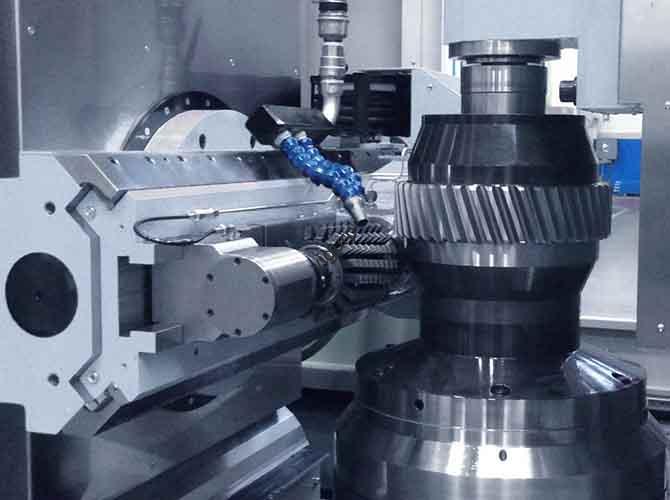
CNC Milling: For Complex Shapes
CNC milling uses rotating tools to remove material from a PTFE block. It’s ideal for 3D shapes, slots, or complex geometries like custom gaskets with multiple holes.
- Pros: High precision (down to ±0.0005 inches ), works for small batches, handles complex designs.
- Cons: Slower than turning for cylindrical parts; needs careful fixturing to prevent slipping.
Use case: A medical device company needed PTFE manifolds with 12 tiny channels, each 0.015 inches wide. CNC milling with a 0.012-inch end mill achieved the precision. A vacuum fixture kept the part from slipping.
CNC Turning: For Cylindrical Parts
CNC turning spins the PTFE while a cutting tool shapes the surface. It’s best for rods, bushings, or valves.
- Pros: Fast for cylindrical parts; smooth outer surfaces.
- Cons: Limited to rotational symmetry.
Key tip: For long PTFE rods (over 6 inches), use a follow rest —a support tool—to prevent bending during spinning.
Drilling: Tricky but Doable
Drilling holes in PTFE is harder than in metal. The material’s softness lets drill bits “walk” (drift off-center) or tear the edges.
Best practices:
- Use a sharp, high-helix drill bit (30-40° helix) to pull chips out fast.
- Start with a smaller pilot hole (50% of final size) to prevent walking.
- Apply light pressure —too much force deforms the PTFE.
Example: A chemical plant needed 1/4-inch holes in PTFE gaskets for bolts. Using a 1/8-inch pilot hole and a high-helix bit reduced inaccuracies from ±0.01 inches to ±0.003 inches .
Routing: For Flat Parts
Routing uses a handheld or CNC router to cut PTFE sheets into flat shapes—like large gaskets or insulators. It’s cost-effective for thin PTFE (0.01-0.5 inches thick ).
- Pros: Fast for large, flat parts; low setup costs.
- Cons: Not for thick PTFE (over 0.5 inches) or tight tolerances (best for ±0.005 inches ).
Critical Challenges and How to Solve Them
Even experienced machinists run into problems with PTFE. Here are the most common issues and proven fixes.
Material Deformation
PTFE’s softness means it can stretch or compress during machining, especially under too much clamping pressure. Parts come out of the fixture out of tolerance.
Solution:
- Use a vacuum fixture (for flat parts) or soft-jaw clamps lined with rubber or felt to distribute pressure evenly.
- Don’t over-clamp. Tighten just enough to hold the part—you should be able to move it slightly with gentle pressure.
Case study: A client was making PTFE washers 0.1 inches thick with CNC milling. 30% were warped after machining. We switched to a vacuum fixture, which applied even pressure across the whole washer, and reduced warpage to less than 5% .
Poor Surface Finish
PTFE can come out “fuzzy” or rough if the tool is dull or the feed rate is too high. A rough finish ruins sealing on gaskets or fluid flow in medical parts.
Solution:
- Use sharp carbide tools. High-speed steel dulls too fast on PTFE.
- Run high cutting speeds (1,500-3,000 RPM for milling) and low feed rates (5-10 inches per minute).
- Add a finish pass —a final light cut with 0.001-0.002 inches depth —to smooth the surface.
Heat Buildup
PTFE’s low thermal conductivity traps heat at the cutting edge. This softens the material (causing deformation) or degrades it (releasing toxic fumes).
Solution:
- Use coolant. Light mineral oil works best. Water-based coolants cause moisture absorption.
- Avoid dry machining. Dry cuts generate 2-3x more heat .
- Monitor temperatures with an infrared thermometer. If it exceeds 200°C , slow the feed rate or increase coolant.
Chip Control
PTFE chips are soft and stringy—not like metal chips that break easily. They can clog tools, scratch surfaces, or jam fixtures.
Solution:
- Use tools with chip breakers (grooves that break up stringy chips).
- Set up a chip suction system to remove chips as they form.
- For turning, use a chip deflector (a small metal plate) to guide chips away.
Best Practices for PTFE Machining
Follow these steps to consistently get high-quality parts.
Choose the Right PTFE Grade
Not all PTFE machines the same:
- Virgin PTFE: Pure, softest, hardest to machine. Best for non-critical parts like simple gaskets.
- Glass-Filled PTFE: Contains 10-40% glass fibers. Stiffer, easier to machine. Ideal for parts needing dimensional stability (bushings).
- Carbon-Filled PTFE: Carbon additives for wear resistance. Machines well but dulls tools faster—use carbide.
Tip: For tight tolerances (±0.001 inches ), avoid virgin PTFE. Use glass-filled or carbon-filled grades.
Prepare the Fixture
- Secure the part: Vacuum fixtures for flat parts, soft-jaw clamps for cylindrical parts.
- Align the part: Use a dial indicator. Even 0.001-inch misalignment can ruin the part.
Select Tools and Parameters
Use this quick-reference table:
| Operation | Tool Material | Speed (RPM) | Feed (IPM) | Depth (inches) |
|---|---|---|---|---|
| Milling (Virgin) | Carbide | 2,000-2,500 | 7-9 | 0.005-0.01 |
| Milling (Glass-Filled) | Carbide | 1,800-2,200 | 8-10 | 0.008-0.012 |
| Turning | Carbide | 2,500-3,000 | 6-8 | 0.005-0.01 |
| Drilling | High-Helix Carbide | 1,200-1,800 | 3-5 | Pilot: 0.003-0.005; Final: 0.001-0.002 |
Monitor the Process
- Check the part every 5-10 minutes for deformation or finish issues.
- Inspect tolerances with calipers or a micrometer. Don’t wait until the batch is done.
Post-Processing
- Clean the part: Use isopropyl alcohol to remove coolant and debris. PTFE is non-porous, so cleaning is easy.
- Dry thoroughly: If you used water-based coolant, let the part air-dry for 24 hours to prevent moisture absorption.
- Inspect for warpage: Lay flat parts on a granite surface plate. If warped, heat gently (100-120°C ) and press flat with a heavy metal plate for 30 minutes.
Yigu Technology’s Perspective on PTFE Machining
At Yigu Technology , we’ve machined thousands of PTFE parts for aerospace, medical, and chemical clients. Our biggest lesson? PTFE machining is about precision, not speed. Rushing—using high feed rates or dull tools—leads to wasted material and rework, which costs more in the long run. We always start with a small test batch (5-10 parts ) to fine-tune parameters before scaling up.
We’ve also found that glass-filled PTFE is the sweet spot for most applications. It’s easier to machine than virgin PTFE, more dimensionally stable, and still retains PTFE’s key properties—chemical resistance and low friction. For clients with ultra-tight tolerances (±0.0005 inches ), we combine 5-axis CNC milling with post-machining inspection on a coordinate measuring machine (CMM) to guarantee accuracy.
Frequently Asked Questions
Can I machine PTFE with a home CNC router?
Yes, but it’s challenging. Home routers typically lack the precision (tolerances are often ±0.005 inches or worse) and cooling systems that PTFE needs. For small, non-critical hobby projects, use a sharp carbide end mill, a low feed rate (5 IPM), and mineral oil coolant. For critical parts, use professional equipment.
What’s the maximum tolerance I can achieve with PTFE machining?
With professional 5-axis CNC machines and glass-filled PTFE, you can hit tolerances as tight as ±0.0005 inches . Virgin PTFE’s softness limits it to about ±0.002 inches practically.
Is PTFE machining toxic?
It can be if you’re not careful. PTFE degrades above 260°C , releasing toxic fumes (like perfluoroisobutylene) that cause “polymer fume fever”—flu-like symptoms. Always use coolant to keep temperatures below 200°C , wear a respirator, and ensure good ventilation.
How much does PTFE machining cost compared to injection molding?
For small batches (under 100 parts), machining is 50-70% cheaper because there’s no mold cost. For large batches (over 1,000 parts), injection molding wins—the mold cost gets spread across more parts. Example: 50 PTFE gaskets cost about $200 to machine vs. $15,000 for a mold plus $50 for parts with injection molding.
Can I machine PTFE into thin parts (under 0.01 inches thick)?
Yes, but it takes extra care. Use a vacuum fixture to prevent bending, a very low feed rate (3-5 IPM), and a finish pass with 0.0005 inches depth of cut . We’ve successfully machined PTFE films as thin as 0.002 inches for electronic insulation parts.
Discuss Your Projects with Yigu Rapid Prototyping
Ready to machine precision PTFE parts for your next project? At Yigu Rapid Prototyping , we’ve manufactured thousands of PTFE components for aerospace, medical, chemical, and industrial clients. Our team can help you select the right grade—virgin, glass-filled, or carbon-filled—optimize your design for manufacturability, and deliver parts that meet your exact specifications, whether you need one prototype or full production runs. We specialize in 5-axis CNC machining , precision turning , and CMM inspection for tight tolerances. We also offer expert guidance on fixturing and cooling to prevent deformation and achieve perfect results. [Contact Yigu Rapid Prototyping today] for a free consultation and quote. Let’s master PTFE machining together.