Introduction
You want to design parts that are accurate, cost-effective, and actually work when they come off the milling machine. Whether you’re working on a prototype, an industrial component, or a custom project, the question is always the same: What do I need to know to get this right the first time? The short answer lies in Design for Manufacturability (DFM) —understanding what milling machines can and cannot do, and making smart choices about materials, tolerances, and geometry. But turning that into a practical, repeatable process takes more than just theory. In this guide, we’ll walk through everything from core principles to real-world fixes, so you can design parts that mill smoothly, avoid costly mistakes, and perform exactly as intended.
What Is Milling Design, and Why Does It Matter?
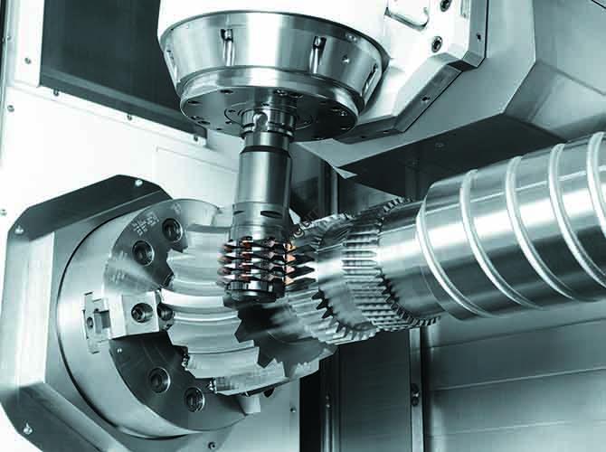
Milling design is the process of creating parts that will be made on a milling machine—a tool that removes material using rotating cutters. Unlike 3D printing, which builds parts layer by layer, milling is subtractive. That means your design has to account for how the cutter moves, what shapes it can create, and how removing material affects the part’s strength.
Why should you care about getting milling design right? Because bad designs lead to real problems:
- Higher costs: Reworking parts that fail during machining—or buying custom tooling to fix design flaws—adds expense fast.
- Project delays: When a shop has to stop and figure out how to mill a tricky feature, your timeline slips.
- Performance failures: Parts with sharp internal corners (which are hard to cut smoothly) or uneven material distribution can crack or wear out early.
Real-World Example: A Lesson in Thin Walls
A few years back, a startup I worked with designed a plastic housing for a sensor. They were proud of the compact design—until the machining shop called. The housing had a 0.5mm-thin wall, and the cutter they needed to use was 1mm in diameter. You can probably guess what happened: the cutter couldn’t make a clean cut without bending or breaking that thin wall. The part kept failing during milling.
We went back to the drawing board and thickened the wall to 1.2mm—just enough to match the cutter’s size and give the material some strength. The next run? Perfect. That one change saved them three weeks of rework and about $1,200 in wasted material and labor. The lesson? Always think about the tool before you finalize the design.
Key Milling Design Principles That Prevent Problems
Whether you’re designing a simple bracket or a complex aerospace part, these four principles will keep you out of trouble. They come from decades of combined experience on the shop floor and in the design office.
1. Design for Manufacturability: Work With the Machine, Not Against It
Design for Manufacturability (DFM) means creating shapes that milling machines can actually produce without heroic efforts. The biggest mistake I see? Designers draw things that are technically possible but ridiculously hard to machine.
Here’s what to avoid:
- Internal corners tighter than your cutter radius: Milling cutters are round. They have a corner radius (the rounded tip). You cannot mill a sharp 90° internal corner—the cutter will always leave a radius. If your design needs a corner, make the radius match the cutter’s radius. For a 2mm cutter, you need at least a 2mm internal corner radius.
- Undercuts: These are recesses or grooves that the cutter can’t reach straight on. Think of a groove cut into the side of a part that’s deeper than the cutter’s reach. Undercuts almost always require expensive custom tooling or multiple setups. Whenever possible, redesign with straight walls or chamfers instead.
- Thin walls or tiny features: Remember the sensor housing story? Walls that are thinner than the cutter diameter are prone to breaking during machining. A good rule of thumb: keep walls at least 1.5 times the cutter diameter. For a 1mm cutter, that means walls of 1.5mm or thicker.
2. Tolerances: Be Realistic About What You Actually Need
Tolerances are the allowable variation in your part’s dimensions. They’re critical—but setting them too tight is one of the fastest ways to blow up your budget.
Most standard CNC mills can hold tolerances of about ±0.005 inches (0.127mm) for everyday parts. That’s plenty for most applications. But if you spec ±0.001 inches (0.025mm) , here’s what happens:
- You need more expensive machines with better calibration.
- The shop has to run slower cutting speeds to avoid vibration that causes errors.
- They’ll need extra quality checks, like measuring every feature on a CMM (coordinate measuring machine).
Here’s a reality check: According to a 2024 study by the American Machinists Society, tightening tolerances from ±0.005 inches to ±0.001 inches increases production costs by 40 to 60 percent on average.
So what should you do? Only put tight tolerances on features that absolutely need them—like a hole that must align perfectly with another part. For everything else, loosen up. Your wallet will thank you.
3. Material Choice: Let the Material Guide Your Design
The material you choose isn’t just about strength or appearance—it directly affects how you design the part. Different materials behave differently under the cutter.
| Material | Milling Behavior | Design Implications |
|---|---|---|
| Aluminum (6061) | Soft, easy to cut | Can have thinner walls (down to 1mm for small parts), complex shapes, tight radii. Great for prototypes. |
| Stainless Steel (304) | Harder, can be brittle | Needs thicker walls (minimum 2mm), larger internal radii to avoid cracking. Good for high-stress parts. |
| Plastics (ABS, Delrin) | Can melt if cut too fast | Avoid deep, narrow slots (they trap heat). Use wider slots, thicker walls (1.5mm min) to prevent warping. |
A real example: A client once designed a marine component in aluminum to save money. Smart, right? But the part would sit in saltwater. Aluminum and saltwater don’t mix—corrosion would kill it in months. We switched to stainless steel, but that meant redesigning: walls went from 1mm to 2.5mm, and internal radii increased from 1mm to 3mm. The result? A part that resists corrosion and doesn’t crack during milling.
4. Tool Path Thinking: Design for Efficient Cutting
The tool path is the route the cutter takes to remove material. A good design minimizes unnecessary moves, which saves time and improves surface quality.
Here’s what to keep in mind:
- Avoid “islands”: These are small, isolated features—like a tiny boss in the middle of a flat surface. They force the cutter to make extra passes. If you can, integrate islands into larger features.
- Use uniform depths: Cutting at a consistent depth is faster because the machine doesn’t have to keep adjusting the Z-axis.
- Add lead-in and lead-out paths: These are small curved or angled paths that let the cutter enter and exit the material smoothly. They reduce tool wear and prevent chatter—that annoying vibration that leaves a rough surface.
Step-by-Step Milling Design Process
Designing a milled part isn’t just about drawing something that looks good. It’s a process. Follow these five steps, and you’ll catch problems before they cost you time and money.
Step 1: Define What the Part Actually Needs to Do
Before you open any CAD software, ask yourself:
- What is this part for? (Hold a sensor? Connect two components?)
- Which features are critical? (A hole that must align perfectly? A surface that needs to be flat?)
- What environment will it live in? (High heat? Saltwater? Vibration?)
- What’s my budget and timeline? (Tighter budgets mean simpler designs.)
Write this down. It’s your roadmap. For example, if you’re designing a part for a car engine (high heat), you’ll prioritize heat-resistant materials like titanium and avoid thin walls that warp.
Step 2: Pick Your Material and Cutter Size
Based on your requirements, choose a material and a standard cutter size. Standard cutters—like 1mm, 2mm, 3mm, or 1/8 inch, 1/4 inch—are cheap and easy to find. Custom sizes? Expensive and slow to source.
Remember: cutter size drives your minimum feature sizes. A 3mm cutter can’t mill a 2mm-wide slot. And that 1.5x rule for wall thickness? Apply it now.
Step 3: Draft in CAD With DFM in Mind
Now you can start modeling. Use CAD software like Fusion 360, SolidWorks, or FreeCAD (great for beginners). As you draw, keep those DFM principles front and center:
- Add internal radii that match your cutter size.
- Keep walls thick enough for your material.
- Avoid undercuts and islands.
- Label critical features with their tolerances (like “Hole: 10mm ±0.005mm”).
Pro tip: Many CAD programs have a DFM check tool. Fusion 360’s “Manufacturability Check,” for instance, will flag features that are hard to mill and suggest fixes. Use it.
Step 4: Simulate the Milling Process (If You Can)
If you’re using CAD/CAM software like Mastercam or Fusion 360, run a simulation. It shows you how the cutter will move through your design. You can:
- Catch collisions (the cutter hitting something it shouldn’t).
- Spot areas the cutter can’t reach.
- Estimate production time.
Another real example: A client designing a complex aluminum gear used Fusion 360’s simulation. It revealed that a small recess in the gear was too deep for their chosen 3mm cutter. We shallow the recess by 1mm, avoided a custom 5mm cutter, and cut production time by two days. Simulation pays for itself.
Step 5: Export the Right File—and Add Notes
When your design is final, export it in a format the shop can actually use. The best choices:
- STEP: Universal 3D format, works with everything. Preferred by most shops.
- IGES: Another universal format, good for older software.
- 2D DWG/DXF: Only for simple parts. For anything complex, use 3D.
And please, include a design notes document. Tell the shop:
- Which tolerances are critical.
- The exact material and grade (e.g., “Aluminum 6061-T6”).
- Any special requirements (e.g., “Surface finish: 1.6μm Ra”).
Common Milling Design Mistakes (And How to Fix Them)
Even experienced designers make mistakes. Here are the most common ones I’ve seen—and how to fix them, based on real projects.
| Mistake | Why It’s a Problem | How to Fix It | Real-World Example |
|---|---|---|---|
| Sharp internal corners | Cutters are round—they can’t cut a sharp 90° corner. You’ll get a radius, and the part won’t match the design. | Match the internal corner radius to your cutter radius. A 2mm cutter needs a 2mm radius. | A client’s bracket had 90° internal corners. We added 2mm radii. The shop milled it perfectly on the first try. |
| Walls too thin for the cutter | Thin walls bend or break during milling. They’re also weaker in use. | Make walls at least 1.5x the cutter diameter. For a 2mm cutter, that’s 3mm walls. | A plastic sensor housing had 1mm walls with a 2mm cutter. We thickened to 3mm—no more breakage. |
| Overly tight tolerances everywhere | Drives up cost and time. Often totally unnecessary for non-critical features. | Use tight tolerances (±0.001–0.003 in) only where it matters. For everything else, use ±0.005–0.01 in. | A client set ±0.001 in for every feature on a bracket. We loosened non-critical ones to ±0.005 in, cutting costs by 35%. |
| Undercuts | Require custom tooling (expensive) or manual finishing (slow). | Redesign to remove undercuts. Use chamfers, straight walls, or external grooves instead. | A gear design had an undercut for a seal. We changed to an external groove—no custom cutter needed. |
| Ignoring plastic shrinkage | Plastic parts shrink as they cool after milling. The final part ends up smaller than your design. | Add a “shrink factor” to your design. For ABS plastic, that’s about 1.5%. | A client’s ABS housing came out 2% too small. We scaled the design up by 2%—the next batch fit perfectly. |
Yigu Technology’s Perspective on Milling Design
At Yigu Technology, we’ve worked with hundreds of clients—from startups to large manufacturers—on milling projects. One lesson stands out above the rest: great milling design balances function and manufacturability. Too many teams focus only on what the part needs to do and ignore how it will be made. That’s when things go wrong.
Here’s what we recommend based on our experience:
- Involve a machinist early. Even a 30-minute call with a shop can reveal simple tweaks—like adjusting a corner radius to use a standard cutter—that save days later.
- Prioritize standardization. Design around common cutter sizes and readily available materials. Custom tooling is a last resort, not a first choice.
- Test with a prototype. Milling a single part lets you catch issues—thin walls, tight tolerances, hidden undercuts—before you commit to full production.
Milling design isn’t just about drawing. It’s about collaborating with the manufacturing process to create parts that work and are easy to make. That collaboration is what turns a good design into a great one.
Frequently Asked Questions
What’s the minimum wall thickness for a milled part?
It depends on your material and cutter size. For most materials, aim for walls that are 1.5 times the cutter diameter. With a 2mm cutter, that’s 3mm walls. For soft materials like aluminum, you can sometimes go as low as 1x the cutter diameter for small parts—but thicker is almost always better for durability.
Can I mill a sharp 90° internal corner?
No, you cannot. Milling cutters have a rounded tip, so the smallest internal corner you can mill equals the cutter’s radius. If you need a sharper corner, you can use a smaller cutter (a 1mm cutter gives a 1mm radius) or add a chamfer instead.
What file format should I send to the machining shop?
STEP is your best bet. It’s a universal 3D format that works with all CAD/CAM software. If the shop uses older systems, send an IGES file. For complex parts, avoid sending only 2D drawings—3D files prevent misinterpretation.
How do I choose tolerances for my milling design?
Use tight tolerances (around ±0.001–0.003 inches or ±0.025–0.076mm) only for features that absolutely need them—like precision holes or mating surfaces. For everything else, use looser tolerances (around ±0.005–0.01 inches or ±0.127–0.254mm) to save time and money.
Do I need to know CAM software to design milled parts?
No, you don’t. Most machining shops have CAM experts who handle tool path programming. But understanding basic CAM concepts—like cutter paths and cut depths—helps you design parts that are easier to machine. If you’re new, ask the shop to review your design for CAM compatibility before you finalize it.
Discuss Your Projects with Yigu Rapid Prototyping
Need help turning your milling design into a real part? At Yigu Rapid Prototyping, we’ve been helping engineers and designers navigate the challenges of CNC machining for years. Our team can review your design, suggest manufacturability improvements, and deliver precision parts that meet your specs—on time and on budget. Whether you need a single prototype or a full production run, we’re here to help. [Contact Yigu Rapid Prototyping today] for a free consultation and quote. Let’s make your next project a success.