Introduction
If you are wondering how to approach copper machining successfully, the short answer is this: You need to prioritize understanding copper’s unique physical properties, choose the right tools and cutting parameters, and proactively address common issues like chip buildup and tool wear. Copper is quite different from harder metals like steel or aluminum. Its high ductility and excellent thermal conductivity require tailored strategies to get great results. Whether you are a hobbyist working on small parts at home or a manufacturer producing high-volume components, mastering these techniques is essential. In this guide, we will break down everything you need to know to achieve precise, efficient results with copper.
What Key Properties of Copper Impact Machining?
Before diving into specific techniques, it is critical to understand why copper behaves the way it does during machining. Its physical traits directly influence everything from tool selection to cutting speeds and the quality of the final surface finish. Here is what you need to know.
- High Ductility: Copper is extremely malleable. This means it tends to bend and stretch instead of breaking away cleanly. This leads to the formation of long, stringy chips that can clog your cutting tools, damage the workpiece, or even pose a safety risk. For example, in a recent project at a precision engineering shop, machinists struggled with chip entanglement when drilling copper fittings—until they adjusted their chip breakers and feed rates.
- Excellent Thermal Conductivity: Copper transfers heat about five times faster than steel and twice as fast as aluminum. While this is a great benefit for electrical components, it is a real challenge for machining. The heat generated during cutting is quickly pulled away from the cutting zone and into the tool itself. This accelerates tool wear and reduces tool life significantly. A study by American Machinist found that tool longevity can drop by 30% when machining copper compared to steel, if heat is not managed properly.
- Low Hardness: With a Brinell hardness of only 35–45 HB, copper is quite soft. This makes it prone to a problem called “galling,” where the material sticks to the cutting tool. This can ruin your surface finish. For instance, a manufacturer of copper electrical connectors noticed scratches on their finished parts until they switched to coated tools and increased their cutting speeds.
- Electrical Conductivity: While not a direct machining challenge, this property means that copper parts often require very tight tolerances, sometimes as tight as ±0.001 inches, to ensure proper electrical performance. Machinists must carefully balance speed with precision to avoid dimensional errors.
What Are the Common Copper Machining Methods?
Not every machining process works equally well for copper. Below is a breakdown of the most popular methods, along with their pros, cons, and best uses.
| Machining Method | Best For | Pros | Cons | Key Tips |
|---|---|---|---|---|
| Milling | Complex shapes like electrical enclosures and heat sinks. | Very versatile for 2D and 3D parts; capable of high precision. | High risk of chip buildup; requires a rigid machine setup. | Use carbide end mills. Set spindle speeds to 1,500–3,000 RPM for roughing. |
| Turning | Cylindrical parts like pipes, bolts, and bushings. | Fast and efficient for high-volume production; creates smooth finishes. | Heat can warp thin-walled parts. | Use positive-rake inserts to reduce cutting forces. Apply coolant continuously. |
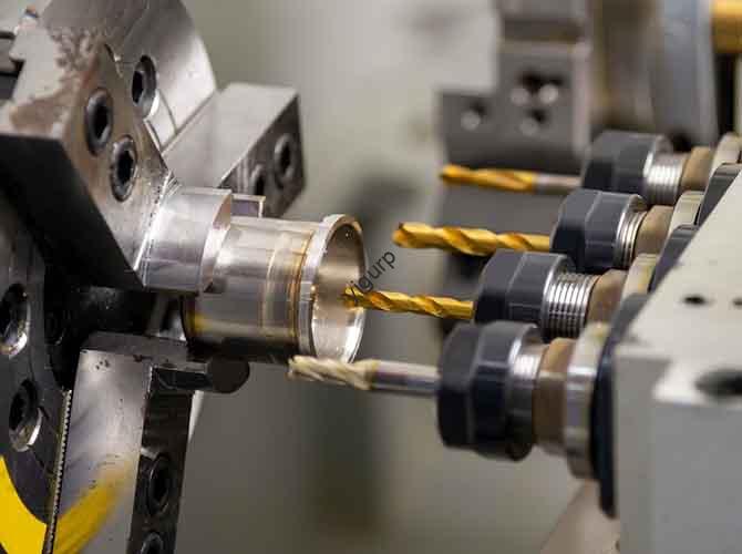
| Drilling | Creating holes, for example in circuit boards or plumbing fixtures. | Simple and cost-effective. | Chips can get stuck in deep holes; small drills risk breaking. | Use twist drills with polished flutes to help chips escape. Start with a pilot hole for deep drilling. |
| Grinding | Achieving ultra-smooth finishes for optical components or medical parts. | Produces extremely tight tolerances (down to ±0.0001 inches); removes burrs. | Slow process compared to others; generates a lot of heat. | Use diamond or CBN (cubic boron nitride) wheels. Keep the workpiece cool with a mist coolant. |
Real-World Example: A manufacturer of copper heat exchangers was struggling with their conventional milling process. They switched to high-speed milling (HSM) for their finned parts. By increasing spindle speeds to 4,000 RPM and using carbide tools with a TiAlN coating, they reduced their cycle time by 40% and completely eliminated chip clogging—all while maintaining a surface finish of Ra 0.8 μm, which was required for efficient heat transfer.
What Essential Tools and Materials Do You Need for Copper Machining?
Choosing the right tools is absolutely critical for successful copper machining. Using tools designed for harder metals will lead to poor results, frustration, and frequent tool changes. Here is what you need in your toolbox.
Tool Materials
- Carbide: This is the most popular and reliable choice for copper. Carbide tools, like those made from tungsten carbide, resist heat much better than HSS and hold a sharp edge for much longer. Look for grades like WC-Co (tungsten carbide-cobalt) for general use—they offer a good balance of hardness and toughness.
- High-Speed Steel (HSS) : HSS tools are suitable for low-volume projects or for machining soft copper alloys like pure copper. They are more affordable than carbide but wear out faster. They are best used for light finishing cuts.
- Coated Tools: Coatings like TiAlN (titanium aluminum nitride) or DLC (diamond-like carbon) are excellent for copper. They reduce friction and help manage heat. One test by Machinery Lubrication showed that TiAlN-coated carbide tools lasted 50% longer than uncoated tools when machining copper.
Cutting Fluids
Using a coolant is non-negotiable for copper machining. It cools the tool, lubricates the cutting zone, and helps flush away chips. The best options are:
- Soluble Oils: These are mixed with water, usually in a 1:10 ratio. They are cost-effective and provide good cooling for general-purpose work.
- Synthetic Coolants: These are ideal for high-speed machining or for parts that need to be very clean, like electrical components. They leave no residue and offer better rust protection than soluble oils.
- Cutting Oils: For heavy-duty operations like deep drilling, cutting oils provide superior lubrication. However, they are messier and more expensive than water-based coolants.
Workholding Equipment
Because copper is soft, it can shift or get damaged during machining if it is not held securely.
- Vise Grips with Soft Jaws: These prevent scratches and distribute clamping pressure evenly, which is critical for thin-walled parts.
- Collets: For turning or milling cylindrical parts, collets offer higher precision and concentricity (down to ±0.0005 inches) than standard chucks.
- Vacuum Chucks: These are best for large, flat parts like copper sheets, where clamps would get in the way of the cutting tool.
A Step-by-Step Guide to Machining Copper Parts
Let’s walk through a practical workflow to help you avoid common mistakes and ensure consistent results. We will use a common project—machining a copper electrical connector—as our example.
- Step 1: Prepare the Workpiece. First, select the right copper alloy. Pure copper (C11000) is very soft and hard to machine. For most projects, it is better to use a brass alloy like C36000, often called “free-machining brass,” which has added zinc to improve chip breaking. Use a bandsaw to cut your stock slightly larger than your final dimensions, leaving about 0.01–0.02 inches for finishing. Finally, mount the workpiece securely in a vise with soft jaws, being careful not to over-tighten and deform the soft metal.
- Step 2: Choose Your Cutting Parameters. Start with these baseline settings and adjust based on your specific tool and alloy. For a general guide: use a spindle speed of 1,500–4,000 RPM, a feed rate of 0.001–0.003 inches per revolution (IPR), and a depth of cut (DOC) of 0.01–0.05 inches per pass. For our example milling a C36000 connector with a TiAlN-coated carbide end mill, we might use 2,000 RPM, 0.002 IPR, and a 0.03-inch DOC for roughing.
- Step 3: Execute the Machining Process. Start with a roughing pass to remove most of the excess material, focusing on speed. Use a climb milling technique, where the tool rotates in the same direction as the feed, to reduce cutting forces and chip buildup. Then, switch to a finishing pass with a slower feed rate and shallower DOC to achieve your desired surface finish. Throughout the process, monitor your chips. If you see long, stringy chips, increase the feed rate or adjust your chip breaker.
- Step 4: Post-Machining Steps. After machining, use a file or deburring tool to remove any sharp edges. This is important because soft copper burrs can cause electrical shorts in connectors. Then, clean the part thoroughly with a solvent like isopropyl alcohol to remove any coolant residue. For critical electrical parts, ultrasonic cleaning is a great option. Finally, inspect all critical dimensions with calipers or a micrometer to ensure they meet your specifications.
What Are the Common Copper Machining Challenges and How Do You Fix Them?
Even experienced machinists run into problems with copper. Here are the most frequent issues and the actionable solutions to fix them.
- Built-Up Edge (BUE) : This is when copper sticks to the tool’s cutting edge. It ruins surface finishes and increases wear. It often happens when cutting speeds are too low or tools are dull. The fix is to increase spindle speed by 20-30% , use a coated tool to reduce friction, and apply plenty of coolant.
- Chip Clogging: Long, stringy chips get stuck in tool flutes. This is caused by copper’s ductility. The solution is to use tools with spiral flutes or positive-rake inserts to help break chips into smaller pieces. You can also increase the feed rate slightly to encourage chip breaking.
- Tool Wear: Tools dull quickly due to heat and abrasion. To fix this, use carbide instead of HSS tools. Reduce your depth of cut to lower heat generation, and replace tools at the first sign of wear, before they ruin a part.
- Workpiece Deformation: Soft copper can bend or warp, especially on thin-walled parts. This is caused by excessive cutting force or heat. The fix is to use a lighter feed rate, secure the part with multiple clamps to distribute pressure, and use a mist coolant to cool without adding weight to the part.
Conclusion
Mastering copper machining is all about understanding and adapting to the material’s unique properties. Its high ductility and thermal conductivity require you to be proactive. By selecting the right tools—like carbide end mills with TiAlN coatings—and using the correct cutting parameters, you can manage common problems like built-up edge and chip clogging. Following a careful step-by-step process, from workpiece preparation to final inspection, will help you produce precise, high-quality copper parts efficiently and consistently.
FAQ
What is the difference between machining pure copper and copper alloys?
Pure copper is very soft and ductile, which makes it prone to built-up edge and chip clogging. Alloys like brass or bronze have other metals added, like zinc or tin, which increase their hardness and make them much easier to machine. For most projects, an alloy is the better choice.
Can I use the same tools for copper and aluminum?
While both are soft, you will get better results with different tools. Copper’s higher thermal conductivity means you need more heat-resistant tools. Carbide or coated tools are a better choice for copper, while HSS tools can work fine for aluminum. You will also need to run copper at lower spindle speeds than aluminum.
How do I achieve a mirror finish on copper parts?
Start by machining the part to a very smooth finish, ideally with an Ra of 0.2 μm or lower. Then, polish the surface using a buffing wheel and a polishing compound like jeweler’s rouge. For an ultra-high gloss, you can do a final polish with a very fine diamond paste.
Is dry machining possible with copper?
It is not recommended. Dry machining leads to excessive heat buildup, which causes rapid tool wear and built-up edge. Using a coolant is essential for managing heat, lubricating the cut, and flushing away chips to get good results and a decent tool life.
Discuss Your Projects with Yigu Rapid Prototyping
Are you planning a project with copper parts? At Yigu Rapid Prototyping, we have extensive experience machining copper and its alloys for a wide range of industries. Our team understands the unique challenges of this material and has the right tools and expertise to deliver high-quality, precise results. We can help you with everything from material selection to design optimization.
Contact Yigu Rapid Prototyping today to discuss your project. Upload your design files for a free, expert quote and design review. Let’s build something great together.