In the fast-moving world of industrial production, why do top-tier automotive and aerospace companies rely so heavily on the CNC turning machining process? Whether it is an engine shaft or a high-pressure fuel nozzle, these cylindrical parts require a level of accuracy that human hands simply cannot match.
The CNC turning machining process is a computer-controlled manufacturing method. It transforms raw metal bars into high-precision, uniform components by rotating the workpiece against a stationary cutting tool. Unlike manual lathes, where quality depends on the operator’s steady hand, CNC turning follows digital “blueprints” to deliver micron-level precision (up to ±0.01mm) every single time.
If you need to produce a thousand identical parts or one complex aerospace fitting, understanding the stages of this process is the first step toward efficient production.
What Is the CNC Turning Machining Process?
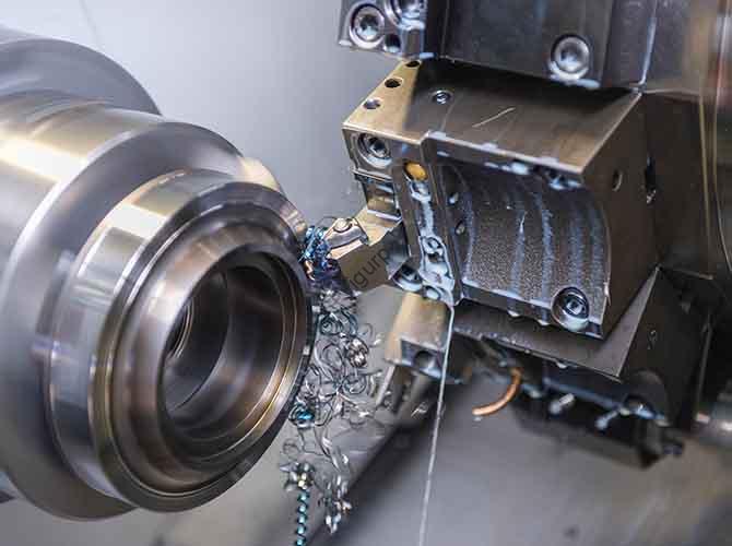
At its core, the CNC turning machining process is a subtractive manufacturing method. A CNC system controls the movement of the machine, spinning a workpiece (usually a metal bar between 5mm and 100mm in diameter) at high speeds. As the part spins, a cutting tool carves away excess material to create circles, tapers, grooves, and threads.
Think of it as a “digital lathe operator.” By using pre-programmed G-code and M-code, the machine manages tool movement, spindle speed, and feed rates 24/7. This consistency makes it the gold standard for creating rotational parts, from tiny electronic pins to massive industrial drive shafts.
6 Core Stages of the CNC Turning Process
A professional workflow is linear and error-proof. Each stage builds on the last to ensure the final part matches your CAD design perfectly.
1. Process Analysis: The Foundation
You cannot start a machine without a plan. This stage defines how the part will be made.
- Drawing Interpretation: We extract details from your 2D or 3D drawings. We look at dimensional tolerances (e.g., 20±0.02mm), surface finish (Ra < 1.6μm), and material types like Aluminum 6061 or Stainless Steel 304.
- Sequence Optimization: We follow the “rough to fine” principle. We remove 90% of the material first during roughing, then refine the details during finishing.
- Common Pitfall: Skipping this step often leads to tool collisions. For example, if you machine threads before drilling a center hole, the part might vibrate and ruin your accuracy.
2. Tool Selection: Matching Tools to Features
The right tool impacts both the speed of production and the quality of the surface.
| Tool Type | Ideal Materials | Key Features | Expert Machining Tip |
| External Turning | All metals | Outer circles, tapers | Use carbide inserts for high-speed aluminum cutting. |
| Drilling Tools | Aluminum, 45# Steel | Through & blind holes | Use indexable drills for holes larger than 10mm. |
| Threading Tools | Steel, Aluminum | M-series threads | Choose TiAlN-coated inserts for tough stainless steel. |
| Grooving Tools | Brass, Aluminum | Snap ring grooves | Keep feed rates low (0.05mm/rev) to prevent breakage. |
3. Cutting Parameter Setting: Speed and Feed
These parameters determine how fast you can go without breaking a tool or melting the plastic.
- Aluminum 6061: Can handle high speeds (150–200 m/min) because it is soft.
- Stainless Steel 304: Requires slower speeds (80–120 m/min) and plenty of coolant to prevent “work hardening.”
- Carbon Steel 45#: Offers a great balance for carbide tools, allowing for deep roughing cuts of up to 4mm.
4. CNC Programming: Translating Design to Code
This is where we turn your ideas into a language the machine understands.
- G-Code: Controls motion (e.g., G01 for linear cutting, G76 for threading).
- M-Code: Controls machine functions (e.g., M03 to start the spindle, M08 for coolant).
- Tip: We always use simulation software like Mastercam or Fusion 360 to “dry run” the program before the tool touches the metal.
5. Workpiece Clamping: Ensuring Stability
If the part vibrates, the finish will be rough.
- Three-Jaw Chucks: Best for round bars; they are fast and self-centering.
- Tailstock Support: If a part is long (more than 5 times its diameter), we use a tailstock to prevent the bar from bending during the cut.
- Runout Check: We use a dial indicator to ensure the part is centered within 0.01mm.
6. Test Cut and Inspection: Final Validation
We never go into mass production without a test.
- The Sample: We machine 1 or 2 parts and check them with micrometers and roughness testers.
- Adjustment: If the test part is 19.95mm instead of 20mm, we adjust the X-axis offset by +0.05mm. This ensures the remaining 9,999 parts are perfect.
Real-World Case: Automotive Aluminum Shafts
An automotive supplier recently needed 10,000 aluminum shafts (20mm x 100mm). The requirements were strict: a tolerance of ±0.02mm and a production time of under two minutes per part.
The CNC Solution:
- Process: We used a G71 roughing cycle to remove material at 3mm depth, followed by a G70 finishing pass.
- Parameters: We set the spindle to 2866 rpm with a feed of 0.2mm/rev.
- The Result: We hit a production time of 1.8 minutes per part. By using carbide inserts, we only had to change tools every 500 parts, keeping the line running smoothly.
Yigu Technology’s Perspective
At Yigu Technology, we view the CNC turning machining process as the backbone of precision manufacturing. Our high-speed lathes, like the YG-T200, are built for this workflow. They feature spindles that reach 6,000 rpm and smart offset systems that auto-correct errors down to ±0.005mm.
We have helped aerospace firms achieve incredible accuracy and assisted automotive clients in cutting production times by 35%. As we move toward Industry 4.0, our machines now use AI-driven suggestions for speeds and feeds, reducing the risk of human error and ensuring that your parts are right the first time.
Conclusion
The CNC turning machining process is far more than just spinning metal. It is a carefully orchestrated dance of software, tooling, and physics. By mastering the six stages—from initial analysis to the final test cut—manufacturers can produce complex, high-quality parts at a speed that manual processes simply cannot match. Whether you are working with aluminum or tough stainless steel, a disciplined approach to CNC turning ensures your project stays on schedule and within tolerance.
FAQ
What is the difference between roughing and finishing in CNC turning?
Roughing removes the most material (80-90%) as quickly as possible, prioritizing speed over looks. Finishing uses a much slower feed and smaller depth to achieve a smooth surface (Ra < 1.6μm) and final precision.
How do I stop tools from breaking when cutting stainless steel?
Stainless steel is hard and generates a lot of heat. Always use TiAlN-coated carbide tools, increase your coolant flow, and reduce your cutting speed compared to what you would use for aluminum.
Can I use CNC turning for plastic parts?
Yes. For materials like POM or ABS, CNC turning is excellent. However, you should use High-Speed Steel (HSS) tools and lower speeds to prevent the plastic from melting during the process.
Why is my surface finish rough after turning?
This is usually caused by a feed rate that is too high or a cutting speed that is too low. Try reducing your feed by 20% or ensuring your tool is sharp. Vibration from poor clamping can also cause a rough finish.
How long does it take to set up a CNC turning job?
For a simple part, setup (including programming and tool loading) usually takes 1 to 3 hours. Once the setup is verified, the machine can run thousands of parts with very little intervention.
Discuss Your Projects with Yigu Rapid Prototyping
Are you ready to bring your cylindrical designs to life with micron-level accuracy? At Yigu Rapid Prototyping, we combine years of engineering experience with the latest CNC technology to deliver parts that exceed expectations. From rapid prototypes to high-volume automotive runs, we are here to optimize your production.
Would you like me to analyze your part drawings to suggest the best tool selection and sequence for your next project?