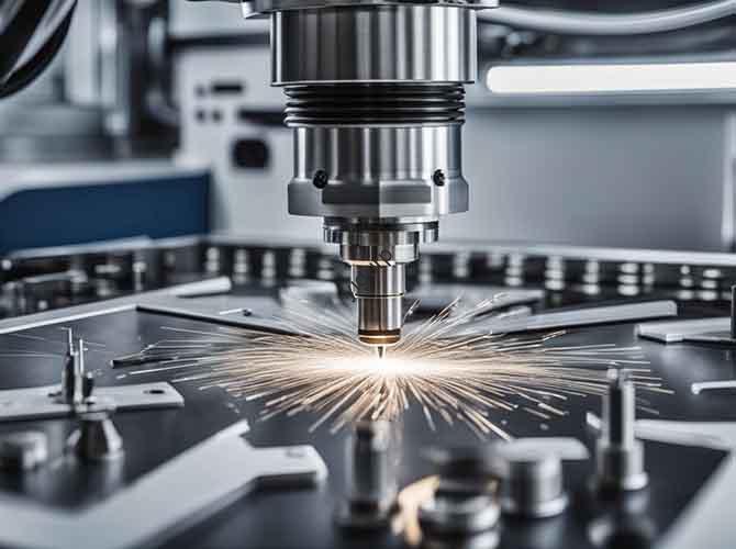
In industries like electronics and automotive parts, CNC Processing Plane Mesh is a vital tool for surface treatment. This method creates a grid-like texture on a part. It makes phone casings look sleek and improves the grip on tool handles. However, getting a perfect grid is hard. If you choose the wrong metal or set the machine poorly, you might break a tool or ruin the part. This guide shows you how to get precision texturing results every time.
How to Prepare for CNC Plane Mesh?
Good prep is the secret to success. If you skip these steps, you will face defects like misaligned meshes. Follow these three tasks before you hit the start button.
Choose the Right Material
The metal you pick changes your speed and tool choice. Each metal has a different hardness level. This affects how the grid forms under the cutter.
| Material Type | Key Properties | Ideal Mesh Uses | Tool Choice |
| Aluminum (6061) | Soft, easy to cut | Phone cases, car trim | Carbide end mills |
| Stainless Steel (304) | Hard, rust-resistant | Medical tools, industrial parts | Titanium-coated carbide |
| Brass (H62) | Malleable, shiny | Decorative parts | High-speed steel (HSS) |
Calibrate Your CNC Machine
Even the best machines need a check-up. A small error can make one side of your grid deeper than the other. Use a precision ball bar to check your X, Y, and Z axes. Your axis deviation must stay below ±0.005mm. Also, check the spindle vibration. It should be under 0.01mm to avoid wavy lines.
Secure the Workpiece Properly
A loose part will shift and ruin the pattern uniformity. For aluminum or brass, a vacuum chuck works best. It keeps the part flat without using clamps that might block the tool. For steel, use mechanical clamps. Tighten them to 25–30 N·m of torque. This stops the part from moving but does not bend the metal.
What are the Core Machining Steps?
Now it is time to cut. This process relies on two things: your tool path design and your machine settings.
Design the Tool Path
The path is the “blueprint” of your mesh. You must create horizontal and vertical lines that intersect perfectly. For a fine texture, set the grid spacing to 0.5–1mm. Ensure a 10% path overlap. This prevents gaps in the final texture. We find it best to cut all horizontal lines first, then do the vertical ones. This reduces tool wear.
Adjust the Machining Parameters
Getting the speed and feed rate right is the most important task. If the spindle is too slow, the metal will tear. If the feed is too fast, the tool might skip.
| Material | Spindle Speed (RPM) | Feed Rate (mm/min) | Cutting Depth (mm) |
| Aluminum 6061 | 3000–4000 | 500–800 | 0.1–0.3 |
| Stainless Steel 304 | 1500–2500 | 200–400 | 0.05–0.2 |
| Brass H62 | 2500–3500 | 400–700 | 0.08–0.25 |
Perform a Scrap Test
Never start on your final part. Use a scrap piece of the same metal first. Measure the mesh depth at five different points. Use a caliper to ensure it matches your CAD design. This test run saves you from wasting expensive materials.
How to Check Your Final Part?
Once the machine stops, you must verify the quality. A quick check stops bad parts from reaching your customers.
Inspect the Grid Visually
Use a 10x magnifying glass. Look for missing lines or uneven gaps. If you see tiny metal flakes or burrs, your tool might be dull. In a recent project, we saw burrs on an aluminum part. We added a small 0.1mm chamfer to the tool path and cut the feed rate by 10%. The burrs vanished immediately.
Measure the Mesh Depth
Use a surface profilometer for the best data. The depth should be within ±0.02mm of your goal. For aluminum parts, you can use 400-grit sandpaper to smooth the edges. Be gentle so you do not change the depth of the grid.
How to Fix Common Mesh Defects?
Even experts face issues. Use this table to fix common texturing problems fast.
| Defect Type | Likely Cause | The Quick Fix |
| Uneven Depth | Loose fixture or bad offset | Reset tool offset; tighten clamps. |
| Gaps in Grid | Low path overlap | Increase overlap to 15% in software. |
| Rough Marks | Slow spindle speed | Boost RPM by 20% and check tool wear. |
Conclusion
Mastering CNC Processing Plane Mesh adds huge value to your products. It combines beauty with function. By choosing the right metal and setting precise machining parameters, you can avoid common defects. Remember, the secret is in the prep and the test run. High-quality precision texturing makes your parts stand out in a crowded market.
FAQ
How long does it take to machine a 100mm mesh?
For aluminum with a fine grid, it takes about 8–10 minutes. Harder metals like stainless steel take 15–20 minutes because you must move slower.
Can I machine plane mesh on curved surfaces?
Yes. You will need a 5-axis CNC machine. This allows the tool to tilt as it follows the curve. You must also use a 3D tool path simulation in your software.
What is the smallest mesh size possible?
The limit is usually 0.3mm with a standard tool. For very small parts like medical gear, we can use 0.1mm spacing with specialized micro-tools.
Discuss Your Projects with Yigu Rapid Prototyping
At Yigu Technology, we have helped over 50 clients with complex CNC Processing Plane Mesh projects. We helped one car parts maker cut defects by 70% just by tuning their stainless steel settings. We now use AI-driven systems to adjust parameters in real time. This cuts our test run time in half. We also offer titanium-coated tool sets for the toughest metals.
Would you like us to review your CAD design and suggest the best mesh settings for your next part?