In the fast-paced world of modern manufacturing, CNC milling machines are the undisputed workhorses. These digital craftsmen transform raw blocks of metal or plastic into complex, high-quality parts with a level of accuracy that manual machining simply cannot touch. By replacing human fatigue with computer-driven commands, CNC milling minimizes error and maximizes output.
But what exactly happens behind those safety doors? What are the core CNC milling machine machining principles that drive such extreme accuracy? Whether you are a veteran engineer or a product manager looking to streamline production, understanding these principles is the key to solving common challenges like setup errors and inconsistent surface quality.
Why Is Pre-Machining Preparation the Foundation of Accuracy?
A perfect part starts long before the spindle begins to rotate. In the world of high-precision manufacturing, the setup phase is where 80% of errors are avoided. Skipping a single check here often leads to expensive rework or scrapped materials.
1. Creating the Digital “Blueprint”
The machining program (usually written in G-code) acts as the machine’s instruction manual. It defines every move, turn, and cut. To build a robust program, you must carefully select three things:
- Tool Selection: You cannot cut steel with an aluminum bit. We choose endmills, drills, or face mills based on the material. For example, High-Speed Steel (HSS) works well for soft aluminum, while Carbide is essential for hardened steel.
- Cutting Parameters: You must set the spindle speed (500–3,000 RPM for most metals), the feed rate (how fast the tool moves), and the depth of cut.
- Path Planning: A smart program maps the tool’s movement to avoid “air cuts.” This efficiency can save 15–20% of total machining time.
Case Study: Consider a 6061 Aluminum block. A veteran operator will program a 10mm carbide endmill at 2,000 RPM with a 2mm depth of cut. This specific balance prevents the aluminum from “gumming up” the tool while maintaining a high removal rate.
2. Securing the Workpiece
If the part moves even a fraction of a millimeter during a cut, the precision is lost. This makes clamping a critical machining principle.
| Clamping Method | Best For | Key Advantage |
| Vise Clamping | Small, rectangular parts | Quick setup; very cost-effective. |
| Vacuum Chuck | Thin or flat parts (like PCBs) | No clamping marks; applies even pressure. |
| Fixture Plates | High-volume auto or aero parts | Repeatable accuracy within ±0.005mm. |
3. Setting the Machine “GPS”
The machine needs to know exactly where the tool is in relation to the part. This is handled by the Coordinate System.
- Absolute Coordinates: All positions are measured from a fixed “Home” position. This is best for large batches to ensure every part is identical.
- Relative Coordinates: Positions are measured from the last point cut. This is faster for small, one-off “job shop” tasks.
Before starting, we use a tool length setter to measure the tool with an accuracy of ±0.001mm. Even a tiny bit of dust on the tool holder can cause “runout,” leading to an uneven surface finish.
How Does the CNC System Deliver Precision During Execution?
Once the operator presses the green button, the CNC system takes over. However, the process is far from “set it and forget it.” Modern machines use real-time feedback to maintain quality.
Fine-Tuning Parameters on the Fly
Advanced CNC mills use sensors to “listen” to the cut. If the machine detects vibration (chatter), the system automatically reduces the feed rate by 10–15%. If thermal sensors show the tool is getting too hot (approaching 500°C), the system increases coolant flow to prevent the metal from warping.
Why is this important? A small 5% error in feed rate can reduce your tool’s life by 30%. By adjusting in real-time, the machine protects your investment and ensures the part meets the target specs.
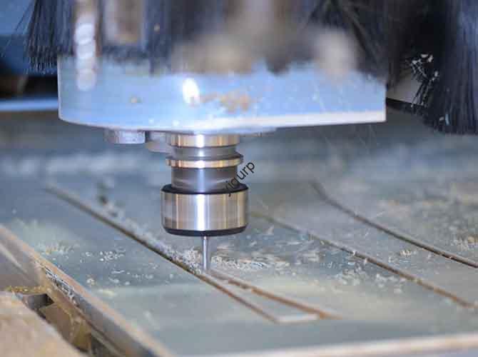
The Layer-by-Layer Removal Process
CNC milling is a subtractive process. The machine follows a specific sequence:
- The tool moves to the starting “Safe” position.
- It dives to the calculated depth.
- It follows the programmed path to contour the shape.
- It retracts slightly between passes. This is crucial for “clearing chips.” If the metal chips aren’t cleared, the tool will recut them, leaving scratches on the part.
Mid-Process Quality Checks
We don’t wait until the end to see if we were successful. A资深 (senior) operator will stop the machine after the first 2-3 passes to measure critical dimensions with a caliper. If the surface looks “grainy” (Ra > 3.2 μm), it usually means the cutting speed is too low, allowing for an easy fix before the part is finished.
What Are the Final Steps to a Perfect Part?
The “machining” might be done, but the part isn’t ready for the customer until it goes through post-processing and machine care.
Removal, Deburring, and Cleaning
When removing the part, always use gloves. The oils from your skin can actually stain certain sensitive metals.
- Deburring: Every cut leaves a tiny “burr” or sharp edge. We use a file or sandpaper to smooth these out. This isn’t just for looks; it ensures the part fits perfectly into its final assembly.
- Cleaning: We use solvents like isopropyl alcohol to strip away sticky coolant residue, leaving a pristine finish.
Essential Machine Maintenance
A CNC mill is a multi-thousand-dollar investment. Neglecting maintenance can drop a machine’s lifespan from 10 years down to 5. After every job, the table must be wiped down and the guide rails must be lubricated. We also inspect the tools for chipped edges. A dull tool is the leading cause of “out-of-tolerance” parts.
Yigu Technology’s Perspective on Milling
At Yigu Technology, we believe the true power of CNC milling lies in the marriage of precision and flexibility. While many shops struggle with the “speed vs. quality” trade-off, we focus on AI-integrated parameter setting. By analyzing the material type and the 3D design before the first cut, our systems auto-adjust for the best feed rates, which has reduced our defect rates by 25%.
For those just starting in the industry, our advice is simple: master a 3-axis CNC mill first. It is more affordable than a 5-axis machine and teaches you the foundational principles of clamping and tool paths. As manufacturing continues to evolve, we remain committed to making high-precision machining accessible to everyone.
FAQ: Answers to Common CNC Milling Questions
What causes a poor surface finish in CNC milling?
The most common culprits are low cutting speeds, dull tools, or a feed rate that is too high. To fix this, try increasing your cutting speed by 10–15% or replacing your tool with a fresh carbide bit.
Can a CNC milling machine work with any material?
Not quite. It excels with metals (Aluminum, Steel, Titanium), plastics (ABS, POM), and wood. However, it is a poor choice for very brittle materials like glass or extremely soft materials like foam, which tend to crumble or deform under the pressure of the tool.
How long does it take to program a part?
For a simple plate with a few holes, a pro can handle the programming in 15–20 minutes. If you use modern CAD/CAM software like Fusion 360, you can often cut that programming time down by another 30%.
Why is my tool breaking during the cut?
This usually happens because the depth of cut is too deep or the coolant isn’t reaching the cutting edge. Ensure you are using the correct “peck” cycle for deep holes and that your coolant nozzles are pointed exactly at the tool tip.
Discuss Your Projects with Yigu Rapid Prototyping
Do you have a complex design that requires the highest level of accuracy? At Yigu Technology, our team of product engineers is ready to help you navigate the world of CNC milling machine machining principles. From material selection to final deburring, we ensure your project is handled with the precision it deserves.
Would you like us to review your CAD files for a free DFM (Design for Manufacturability) analysis? Let’s build your next precision component together.