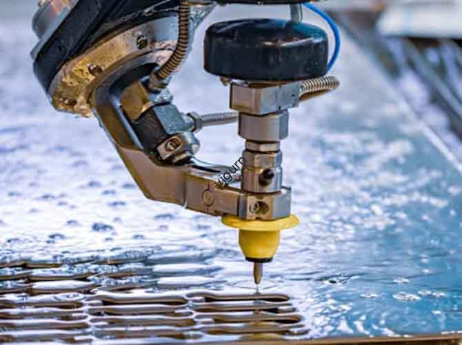
Introduction
In CNC milling, G code for milling is the bridge between your design and the machine tool. It tells the machine where to move, how fast to go, and what path to follow. Good G-code gives you precision, efficiency, and consistent quality. Bad G-code causes crashes, scrap parts, and wasted time. Whether you are a beginner learning to program or an experienced operator looking to optimize, understanding G-code is essential. This guide will walk you through the basics, core instructions, practical applications, common pitfalls, and optimization strategies. You will learn how to write G-code that makes your milling jobs faster, more accurate, and more reliable.
What Is G-Code and Why Is It Essential for Milling?
G-code is the standardized programming language used to control CNC machines. In milling, it is a set of instructions that define tool movements, cutting parameters, and machine functions. It tells the machine things like “move to this point in a straight line,” “cut an arc,” or “turn on the coolant.”
Core Facts
According to the ISO 6983 standard, G-code instructions are numbered from 00 to 99, each with a specific function. The most common milling G-codes are in ranges like 00-04 (motion control), 20-21 (units), 40-42 (tool compensation), 54-59 (coordinate systems), and 90-91 (coordinate modes). These core instructions are compatible across over 95 percent of mainstream CNC systems—Fanuc, Siemens, Mazak, Haas—making G-code a universal language.
Why Milling Relies on G-Code
Milling requires precise control of tool paths. Manual operation cannot achieve the accuracy needed for complex contours or small features. G-code solves this:
- Controllable accuracy: Errors can be held to 0.001mm, essential for precision parts like mold cavities and aerospace components.
- Efficiency: Automated machining is 3 to 5 times faster than manual, and machines can run 24/7.
- Consistency: The same G-code produces identical parts batch after batch, with scrap rates under 1 percent.
- Complexity: G-code can create straight lines, arcs, helices, and other complex trajectories for any milling operation.
Experience case: A mold shop tried manual milling for a complex cavity with 0.005mm tolerance. Pass rate was only 30 percent. After switching to standard G-code programming, pass rate jumped to 99.2 percent, and machining time per mold dropped from 8 hours to 2.5 hours.
How Hard Is It to Learn?
Many beginners worry about difficulty. In reality, you only need about 20 core instructions for most milling work. The learning curve is manageable:
- Basic instructions (G00, G01): 1–2 days.
- Complex instructions (arcs, compensation): 1–2 weeks with practice.
- Advanced cycles (hole machining): Requires experience, but you can start with simple versions.
Industry data shows that with systematic training, novices can program simple milled parts in about one month.
What Are the Core Milling G-Codes and How Do You Use Them?
Here are the most important G-codes for milling, with functions, formats, and practical examples.
Motion Control G-Codes
| Code | Function | Format | Practical Tips | Example |
|---|---|---|---|---|
| G00 | Rapid positioning (no cutting) | G00 X_ Y_ Z_ | Moves at machine’s maximum speed. Always ensure a safe distance (5–10mm) from workpiece and fixtures to avoid collisions. | Moving from machine origin to start point (X10Y10Z5) takes 0.8 seconds—10× faster than manual. |
| G01 | Linear interpolation (cutting feed) | G01 X_ Y_ Z_ F_ | Must include F for feed rate (mm/min). Adjust F by material: aluminum F800–1200, steel F300–500. Slow at corners to avoid impact. | Milling a step on 45 steel from (X10Y10Z5) to (X50Y10Z5) at F400. Flatness error 0.01mm, meeting spec. |
| G02/G03 | Circular interpolation (clockwise/counterclockwise) | G02 X_ Y_ I_ J_ F_ (G03 for CCW) | I, J are center coordinates relative to start. Do not omit; use I0J0 if center coincides with start. Reduce feed by 20–30% vs. straight cuts. | Cutting an R10 arc on aluminum: start (X50Y10), end (X30Y30), center (X50Y30). “G02 X30 Y30 I0 J20 F1000”. Error 0.008mm, Ra1.6. |
| G04 | Dwell (pause) | G04 P_ (P in ms) or X_ (X in s) | Used for hole bottom smoothing, corner dwell to reduce inertia effects. Typical dwell: 0.1–5s. Too long hurts efficiency. | Deep hole milling: pause 0.5s at bottom. “G01 Z-20 F300; G04 P500”. Bottom flatness improved 40%. |
Programming and Setup G-Codes
| Code | Function | Format | Application | Notes |
|---|---|---|---|---|
| G20/G21 | Unit selection (inch/mm) | G20; or G21; | G21 (mm) for most work. G20 (inch) for some export jobs. | Set at program start. Do not switch mid-program. Mistake causes size errors (1 inch = 25.4mm). |
| G90/G91 | Coordinate mode (absolute/incremental) | G90; or G91; | G90 (absolute) for most milling—coordinates based on workpiece zero. G91 (incremental) for local moves, repeats. | Beginners should prefer G90 to avoid confusion. Switching modes requires careful coordinate tracking. |
Tool Compensation and Coordinate System G-Codes
These are critical for accuracy.
| Code | Function | Format | Practical Points | Troubleshooting |
|---|---|---|---|---|
| G40/G41/G42 | Tool radius compensation (cancel/left/right) | G41 G01 X_ Y_ D_ (G42 for right) | Activate before cutting, cancel after. D number must match tool radius in machine. Initial move should be > tool radius to avoid overcut. For inner contours, prefer G41; for outer, G42. | Part 0.8mm undersize? Forgot compensation. Add “G42 G01 X10 Y10 D1 F800;” (D1=4mm). Error now <0.01mm. |
| G54–G59 | Workpiece coordinate systems (6 available) | G54; (activates that system) | Set origin by tool-setting (manual or probe). Use different systems for multiple parts on same table. Activate at program start. | Machining 3 parts? Set origins at G54, G55, G56. Switch via “G54;”, “G55;”, “G56;”. Changeover time cut 60%. |
What Is the Difference Between G-Code and M-Code?
Many newcomers confuse G-code and M-code. They are partners with different roles.
- G-code (preparatory function): Controls tool motion, path, and machining parameters. It runs continuously during cutting.
- M-code (miscellaneous function): Controls auxiliary machine functions—spindle on/off, coolant, program end. It executes one action at a time.
| Dimension | G-Code | M-Code |
|---|---|---|
| Core function | Tool trajectory, cutting parameters | Machine switches, auxiliary actions |
| When used | During cutting, positioning | Before/after cutting, between operations |
| Examples | G00, G01, G02, G41, G54 | M03 (spindle forward), M08 (coolant on), M30 (program end) |
| Execution | Continuous, linked to feed | Single action, wait for completion |
Case study: In a typical milling program:
G21 G90 G54;   (Metric, absolute, set coordinate system)
M03 S2000;     (Spindle on, 2000 RPM)
M08;           (Coolant on)
G00 X10 Y10 Z5;(Rapid to start)
G41 G01 X10 Y10 Z-5 D1 F800; (Left compensation, cutting)
...
G00 Z50;       (Retract tool)
M05;           (Spindle off)
M09;           (Coolant off)
M30;           (Program end)
G-code and M-code work in perfect sync.
Is G-Code the Same on All CNC Machines?
Versatility: Core G-Code Is Universal
Thanks to the ISO 6983 standard, core G-codes (G00, G01, G02, G21, G40–G42, G54–G59, etc.) are compatible across over 95 percent of CNC systems worldwide. A program written for a Fanuc machine will run on Siemens, Mazak, or Haas with minimal changes.
Fact: An operator wrote an aluminum face-milling program on a Fanuc control. To run it on a Siemens 828D machine, they only needed to adjust spindle speed and feed rate—the G-code itself required less than 5 percent modification.
Specificity: Some Codes Are System-Specific
Advanced functions often use non-standard G-codes that differ between systems.
| System | Exclusive Code | Function | Note |
|---|---|---|---|
| Fanuc | G73 | High-speed peck drilling cycle | Not available on Siemens; use CYCLE83 instead. |
| Siemens | G71 | Cylindrical roughing cycle | Programming format completely different from Fanuc. |
| Haas | G87 | Back boring cycle | Other systems need to combine basic codes to achieve same function. |
Professional advice: For cross-machine programs, stick to ISO standard codes. If you must use advanced cycles, consult the target machine’s manual and adapt the format.
How Can You Optimize G-Code for Better Efficiency and Quality?
At Yigu Technology, we see G-code as more than just a language—it is a tool for cost reduction and competitiveness. Well-written G-code delivers three benefits:
- Higher accuracy: Proper compensation, coordinate setting, and path optimization can cut defect rates by over 30 percent.
- Faster cycles: Streamlining empty moves (G00 paths) and optimizing feed rates can shorten machining time by 15–25 percent.
- Longer tool life: Smooth transitions (using G02/G03 arcs instead of sharp corners) and balanced cutting loads reduce tool wear by over 20 percent.
Optimization Tips
- Streamline rapids: Plan G00 paths to be as short as possible. Avoid unnecessary back-and-forth.
- Match feed to operation: Higher feeds for roughing, lower for finishing.
- Use canned cycles: For hole patterns, use drilling cycles instead of many lines of basic G-code. This reduces program length and improves coherence.
- Smooth corners: Replace sharp corners with G02/G03 arcs to avoid sudden speed changes and tool impact.
- Leverage multiple coordinate systems: Use G54–G59 for multiple parts on the same table. Reduces reprogramming and tool-setting during changeover.
Conclusion
G code for milling is the essential language of CNC machining. It translates your design intent into precise machine motions. Mastering the core instructions—motion control, coordinate setting, tool compensation—gives you control over accuracy, efficiency, and quality. Understanding the difference between G-code and M-code keeps your programs organized and safe. Knowing which codes are universal and which are system-specific helps you work across different machines. And applying optimization techniques turns good programs into great ones—saving time, extending tool life, and reducing scrap. Whether you are a beginner or a seasoned pro, a solid grasp of G-code is the foundation of successful milling.
FAQ About G Code for Milling
Q1: What is the core difference between G00 and G01?
A: G00 is for rapid, non-cutting movement. It moves at the machine’s maximum speed. G01 is for cutting feed. It moves at a programmed feed rate (F) and is used for actual material removal. Use G00 for positioning, G01 for cutting.
Q2: What instructions should a beginner learn first?
A: Start with basic setup: G21 (metric), G90 (absolute), G54 (coordinate system). Then learn motion: G00 (rapid), G01 (linear). Next, tool compensation: G40–G42. Then arcs: G02/G03. Finally, canned cycles. Learn by doing: write simple programs and run them on a machine or simulator.
Q3: Why does my part have overcut errors when using G41/G42?
A: Common causes: wrong compensation direction (G41 vs G42), compensation value too large for inner contour, or initial move too short. Check your D value. For inner contours, ensure the tool radius is smaller than the contour radius. Make the initial move longer than the tool radius.
Q4: Does G-code change for different materials?
A: The G-code instructions themselves do not change. But the feed rate (F) and spindle speed (S) must be adjusted. For aluminum: F800–1200, S1500–3000. For steel: F300–500, S800–1500. For copper: F600–900, S1200–2500.
Q5: How do I set the G54 workpiece coordinate system?
A: (1) Home the machine. (2) Mount workpiece and tool. (3) Manually move tool to workpiece zero. For X, touch tool to workpiece side, record machine coordinate, enter in G54 X. Repeat for Y and Z. (4) Verify with a test move: G00 X0 Y0 Z5 should bring tool to workpiece zero.
Q6: Will my G-code run on any CNC mill?
A: Core ISO G-code (G00, G01, G21, etc.) will run on over 95% of machines. But system-specific codes (like Fanuc’s G73) will not. If you need to run a program on a different machine, stick to standard codes or adapt the non-standard parts.
Q7: What is G04 used for?
A: G04 is a dwell, or pause. Common uses: (1) At the bottom of a deep hole, to let chips clear and ensure a flat bottom. (2) At sharp corners, to reduce inertia effects. (3) When the tool first engages the workpiece, to stabilize the cut. Typical dwell times: 0.1–2 seconds.
Q8: How can I make my milling G-code more efficient?
A: (1) Optimize rapid paths—shortest distance. (2) Use appropriate feed rates for each operation. (3) Use canned cycles for repetitive operations like hole drilling. (4) Replace sharp corners with arcs to maintain constant speed. (5) Use multiple coordinate systems for multi-part setups. These optimizations can cut cycle time by 15–25%.
Discuss Your Projects with Yigu Rapid Prototyping
At Yigu Rapid Prototyping, we are experts in G code for milling and all aspects of CNC machining. Our programmers write optimized code that balances speed, accuracy, and tool life. Our shop is equipped with modern CNC mills from Fanuc, Siemens, and other leading controls. We handle complex parts for aerospace, medical, automotive, and industrial clients. Whether you need a one-off prototype or a high-volume production run, we deliver precision and reliability. Contact Yigu today to discuss your project and get a free quote.