In the fast-paced world of mechanical manufacturing, precision is not just a goal—it is a requirement. Whether you are building a high-speed engine or a delicate medical tool, the fasteners holding everything together must be perfect. Today, over 95% of high-precision producers have abandoned traditional manual lathes in favor of CNC machining male threads.
But why is this shift so dramatic? The answer lies in the persistent “pain points” of old-school manufacturing. Manual threading often results in inconsistent dimensions, slow output, and high tool costs. CNC machining male threads solves these issues by using computer-controlled automation to deliver flawless, external threads on cylindrical parts like bolts, studs, and shafts. This guide explores the technology, the benefits, and the professional steps needed to master this essential industrial process.
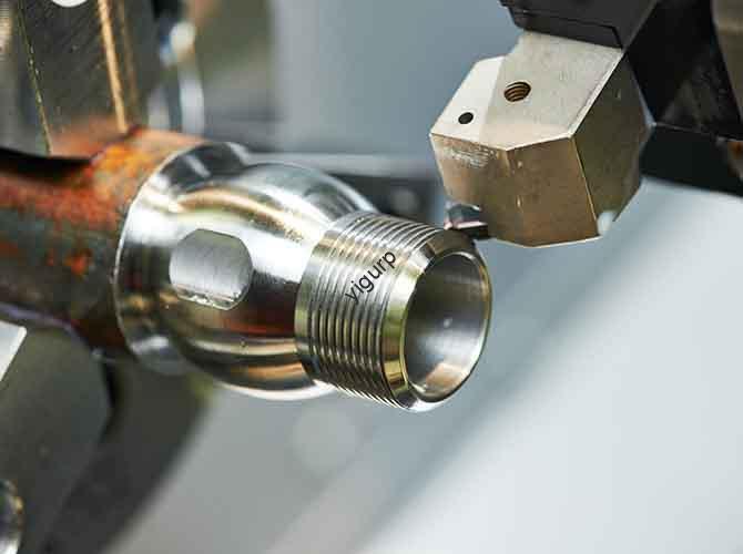
What Is CNC Machining Male Threads?
At its core, CNC machining male threads is an automated process where a Computer Numerical Control (CNC) lathe cuts helical grooves into the outside of a workpiece. Unlike manual threading—where a person’s hand-eye coordination determines the quality—CNC systems follow a digital script.
These systems use specific G-codes (like the famous G76 cycle) to guide the tool. This ensures that every single thread has a uniform pitch, diameter, and depth. In industries like aerospace, a deviation of just 0.01mm can lead to assembly failure. CNC’s ability to maintain a tolerance of ±0.005mm makes it the backbone of modern mechanical connections.
Why Does Precision Matter for Fasteners?
Threads are the primary way we join parts that need to stay together under pressure. If the major diameter is too small, the bolt will wobble. If the pitch is inconsistent, the nut will jam. CNC automation removes the “human factor,” ensuring that the first part and the ten-thousandth part are identical.
CNC vs. Traditional Threading: Which Wins?
Choosing the right method affects your bottom line and your product’s reputation. Below is a comparison showing why CNC is the industry standard for industrial fasteners.
| Feature | CNC Machining Male Threads | Traditional Manual Lathe |
| Accuracy | ±0.005mm pitch tolerance; perfect consistency. | ±0.05mm variation; high error risk. |
| Production Speed | 30–40 parts per hour; very efficient. | 8–12 parts per hour; slow and manual. |
| Tool Wear | Low; even feed rates double tool life. | High; uneven pressure dulls tools fast. |
| Complexity | Handles multi-start and variable pitches. | Limited to basic, single-start threads. |
| Labor | 1 operator can run 3 machines at once. | 1 highly skilled master per machine. |
How to Machine Male Threads?
To achieve professional results, you must follow a linear, logical workflow. Skipping a step in the CNC machining process can lead to expensive scrap metal.
1. Define Your Thread Parameters
Before you touch the machine, you need a clear checklist of specifications:
- Major Diameter: The outer width of the thread (e.g., 8mm for an M8 bolt).
- Pitch: The distance between two thread peaks (e.g., 1.25mm).
- Direction: Most are right-hand threads, but some rotating parts need left-hand threads.
- Material: Is it soft aluminum or hard titanium? This decides your tool and speed.
2. Select the Best Threading Tool
Your tool choice is the “make or break” factor for surface finish. You must match the tool material to your workpiece.
- For Aluminum (Soft): Use High-Speed Steel (HSS). It has very sharp edges that prevent “tearing” the soft metal.
- For Steel (Medium-Hard): Use Carbide Inserts. These are heat-resistant and perfect for high-speed production.
- For Titanium (Hard): Use Cermet Inserts. These can withstand extreme heat (up to 1,200°C) without chipping.
3. Write and Debug the CNC Program
The G76 cycle is the most common way to program threads. It automates the multiple passes needed to reach the final depth.
Example Pro-Tip: In your G76 line, the “P” value controls the finish. Setting it correctly can eliminate burrs before the part even leaves the machine.
4. Test on Scrap Material
Never run a high-value workpiece first. Use a scrap piece to verify the dimensions with a ring gauge. If the gauge doesn’t spin on smoothly, adjust your X-axis offset in the CNC control to change the thread depth.
How to Optimize Your Parameters?
Getting the numbers right prevents tool breakage and ensures a smooth surface roughness (Ra < 1.6 μm). Here are the optimized ranges for common industrial metals:
| Parameter | Aluminum | Steel | Titanium | Fix for Issues |
| Spindle Speed | 80–120 m/min | 150–200 m/min | 100–150 m/min | If chattering, slow down 15%. |
| Feed Rate | 1.0–1.5 mm/rev | 0.8–1.2 mm/rev | 0.6–1.0 mm/rev | If misaligned, reduce feed. |
| Passes | 4–6 | 5–7 | 6–8 | If burrs appear, add 1 pass. |
Where Are CNC Male Threads Used?
The versatility of CNC machining allows it to serve diverse sectors with extreme reliability.
1. Automotive Performance
Engine bolts, such as M10×1.5mm, must survive high torque and 150°C heat. One supplier we know uses CNC to produce 10,000 bolts daily with a defect rate of nearly zero. This keeps production lines moving without assembly delays.
2. Aerospace Reliability
Aircraft wings are held together by titanium studs. These parts face massive pressure changes at 30,000 feet. CNC machining is the only way to hit the ±0.003mm tolerance required for flight safety.
3. Medical Precision
Surgical tools often use stainless steel threaded shafts. These threads must be incredibly smooth (Ra 0.8 μm) to prevent irritating human tissue. CNC precision ensures that medical tools assemble and disassemble perfectly every time.
Expert Insights from Yigu Technology
At Yigu Technology, we believe that a thread is only as good as the machine that cuts it. We have integrated real-time tool wear sensors into our CNC lathes. These sensors alert the operator before a tool fails, saving the part from being ruined.
For our clients, we often suggest using preset thread cycles. These can cut your programming time by 30%. Whether you are making tiny M3 screws for electronics or large shafts for heavy machinery, the secret is in the stability of the machine and the accuracy of the code. We have helped firms move from 10% scrap rates to 0.05% just by optimizing their CNC threading parameters.
Conclusion
CNC machining male threads has transformed the world of industrial fasteners. By moving away from manual guesswork and toward automated precision, manufacturers can produce stronger, more reliable connections. From choosing the right carbide insert to mastering the G76 code, every detail contributes to the final quality. If you value efficiency and accuracy, CNC is the only path forward.
FAQ
What is the smallest thread size a CNC can make?
Standard CNC lathes easily handle M1 threads (1mm diameter). For micro-electronics, specialized machines can go as small as M0.5 with high-precision spindles.
Can I machine threads on plastic like PEEK?
Yes. For PEEK or PVC, use a very sharp tool and slow your spindle speed (50–70 m/min). This prevents the plastic from melting or tearing during the cut.
Why are my threads coming out rough?
This is usually caused by a speed that is too slow or a dull tool. Try increasing your spindle speed by 10% or adding a final “spring pass” with zero depth to clean the surface.
How long does it take to learn CNC threading?
A basic operator can learn to load programs and run parts in 2 weeks. Mastering the ability to write code and optimize for hard metals like titanium usually takes about 1 month.
What is the difference between major and minor diameter?
The major diameter is the “crest” or the widest part of the thread. The minor diameter is the “root” or the deepest part of the cut.
Discuss Your Projects with Yigu Rapid Prototyping
Are you ready to elevate your fastener production? At Yigu Rapid Prototyping, we specialize in high-precision CNC machining male threads for the world’s most demanding industries. Our advanced facility ensures your parts are delivered with ±0.003mm accuracy and superior surface finishes. Whether you need a small batch of titanium studs or mass production of automotive bolts, we are here to help.
Would you like me to review your thread specifications to ensure they are optimized for CNC production?