CNC lathe ball head processing uses Computer Numerical Control (CNC) to machine workpieces into spherical shapes. In the past, manual lathes relied on the steady hand of a master machinist. Today, we use pre-programmed code to control every move of the cutting tool.
The principle is simple. A CNC system reads a digital design, such as a CAD file. It then directs the lathe’s tool to follow a curved, spherical path. This removes the risk of human error. It allows a factory to produce 1,000 identical parts with the exact same accuracy every time.
Why Is This Process Essential?
- Uniformity: Every part in a batch matches the digital blueprint.
- Complexity: It can handle spherical shapes that are impossible to make by hand.
- Efficiency: Once the program is set, the machine runs automatically, saving labor costs.
What Is the Step-by-Step Workflow?
To get consistent results, you must follow a linear path. Skipping a single check can lead to broken tools or scrap metal. Here is the professional workflow for CNC lathe ball head processing.
1. Precision Programming
First, you write the machining program using software like Mastercam or UG. You must input the exact spherical dimensions, including diameter and radius. You also choose the cutting path to ensure the tool does not hit the machine’s chuck. A good program is the foundation of a good part.
2. Secure Workpiece Clamping
Next, you lock the raw material into the lathe’s chuck. This step is critical for stability. Use a dial indicator to check for “runout.” You want the material to spin with less than 0.01mm of wobble. If the clamping is too loose, the part will fly out. If it is too tight, you might deform a hollow workpiece.
3. Tool Setting and Calibration
You must tell the machine exactly where the tool is. This is called tool setting. You can do this by making a small trial cut or by using a digital tool presetter. Recording these “offsets” ensures the tool starts cutting at the perfect spot. Expert shops use presetters to cut setup time by about 30%.
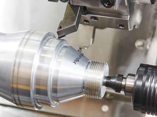
4. Automatic Machining
Now, the machine takes over. As it runs the program, the operator must listen for abnormal noises. A high-pitched squeal often means the tool is wearing out. For tough metals like titanium, you may need to slow down the feed rate mid-process to maintain a smooth finish.
5. Final Quality Inspection
The job isn’t done until you verify the numbers. Use a micrometer to check the diameter. A roundness tester will tell you if the sphere is perfectly symmetrical. If the radius is off, you must troubleshoot the program before running the next part.
What Are the Critical Success Factors?
To solve common problems like rough surfaces or broken tools, you must balance four key factors.
| Critical Factor | Impact on Quality | Expert Optimization Tips |
| Tool Selection | Affects surface finish and tool life. | Use Carbide for steel; HSS for aluminum. Choose tools with a sharp nose radius. |
| Cutting Speed | Determines how fast you finish. | Aim for 150-200 m/min for aluminum; 80-120 m/min for steel. |
| Feed Rate | Controls the surface smoothness. | Keep it between 0.1-0.2 mm/rev. Slower is better for a “mirror” finish. |
| Cooling | Prevents heat damage and warping. | Use high-flow coolant (> 5 L/min). Use mineral oil for aluminum to prevent sticking. |
Where Is This Technology Used?
Because of its high precision, CNC lathe ball head processing is a staple in several high-tech industries.
Aerospace Components
In aircraft engines, valve balls must handle extreme heat and pressure. CNC processing ensures a tolerance of 0.003mm. This prevents dangerous fuel leaks in flight. These parts often use Inconel or other super-alloys that only a CNC lathe can handle accurately.
Automotive Steering Systems
The ball heads in your car’s steering and suspension are made this way. One major car brand produces 5,000 steering ball heads every day using this method. By using CNC, they keep their defect rate below 0.1%, ensuring your car stays safe on the road.
Industrial Robotics
Robots need smooth joints to move precisely. CNC processing creates spherical joints with a surface roughness (Ra) of 0.8 μm. This low friction extends the life of the robot and reduces the energy needed for movement.
Future Trends in Spherical Machining
The industry is moving toward “Smart Machining.” We are seeing lathes equipped with AI-driven sensors. These sensors feel the vibration of the tool. If they detect a tool is about to break, they automatically stop the machine. This prevents a broken tool from ruining an expensive part.
Another trend is 5-axis spherical turning. This allows the tool to move even more freely, creating complex “balls” that aren’t perfectly round, such as elliptical joints for medical implants.
Insights from Yigu Technology
At Yigu Technology, we consider ball head processing to be the backbone of our precision work. We have helped hundreds of clients, from small startups to global automotive suppliers. The most common mistake we see? Choosing the wrong clamping pressure.
Many operators forget that metal expands when it gets hot during cutting. If the clamp is too tight, the sphere becomes an oval once it cools down. We use smart sensors in our lathes to monitor this in real-time. This approach helped one client cut their production time by 25% while actually increasing their part accuracy. In this business, the smallest details make the biggest difference.
Conclusion
CNC lathe ball head processing is the gold standard for creating round, high-precision parts. By combining a digital blueprint with rigid machines and the right cutting parameters, you can achieve results that manual labor simply cannot touch. Remember to focus on your tool offsets and clamping stability. These are the two areas where most errors occur. With the right setup, you can turn a difficult design into a repeatable, profitable reality.
FAQ
What is the typical tolerance for a CNC ball head?
Most standard setups achieve ±0.005mm to ±0.01mm. For critical medical or aerospace parts, high-end lathes like our YG-2000 series can hit ±0.002mm.
How long does it take to machine one part?
It depends on the size. A small 10mm aluminum ball might take only 2 minutes. A large 50mm steel sphere could take 10 minutes due to the extra material that needs removal.
Can I machine plastic ball heads?
Yes. Materials like PEEK or Delrin are very common. Use a lower cutting speed (50-80 m/min) and avoid heat to prevent the plastic from melting.
What is “Runout” and why does it matter?
Runout is how much the material wobbles as it spins. Even a tiny wobble will make your “sphere” look like an egg. Always use a dial indicator to verify the part is centered.
Do I need a special tool for spherical turning?
While standard tools work, specialized button inserts or “full radius” tools are best. They follow the curve more naturally and leave a better surface finish.
Discuss Your Projects with Yigu Rapid Prototyping
Are you looking for a partner to handle your most difficult spherical parts? At Yigu Rapid Prototyping, we specialize in CNC lathe ball head processing for the aerospace, medical, and automotive sectors. Our facility is equipped with the latest smart lathes to ensure your parts are delivered on time and within spec. Whether you need a single prototype or a batch of 10,000, we provide the expertise to get it right the first time.