In the fast-paced world of modern manufacturing, the CNC five-axis linkage machining prototype has emerged as a game-changing technology. It enables the creation of high-precision, complex components that traditional 3-axis machining simply cannot match. By combining three linear axes (X, Y, Z) with two rotary axes, this method delivers unmatched flexibility. It is the perfect solution for parts with intricate curved surfaces, angled holes, or multi-sided features found in aerospace, automotive, and medical industries.
For product engineers testing new designs or procurement specialists sourcing reliable prototypes, understanding the ins and outs of this process is the key to success. It helps you avoid delays, reduce material waste, and ensure final parts meet strict performance standards. This guide breaks down the entire process, offering actionable data and real-world examples to help you navigate your next project with confidence.
Why Is Design and Programming the True Foundation?
The success of any CNC five-axis linkage machining prototype starts long before the machine begins to hum. Precise design and programming are non-negotiable. Skipping these steps or cutting corners leads to misaligned features, rough surfaces, and costly machine damage.
3D CAD Design: Modeling Every Detail
First, you must use CAD (Computer-Aided Design) software like SolidWorks, AutoCAD, or Fusion 360 to create a high-fidelity 3D model. In a five-axis environment, this means defining every complex feature with absolute clarity:
- Curved Surfaces: You must specify exact radii, tangency, and arc lengths. This is critical for parts like turbine blades or automotive wheel arches where aerodynamics matter.
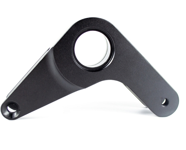
- Angled Holes: Precisely mark positions and angles relative to the main body. For example, a 45° hole in a bracket must align perfectly with its mating part.
- Multi-Sided Features: Model all sides of the prototype, as the five-axis machine will access these areas in a single setup.
Engineer’s Note: A medical device manufacturer once missed a 0.2mm error in a CAD model for a surgical tool handle. Because the curve was slightly off, the prototype didn’t fit the ergonomic grip design. This tiny oversight delayed testing by 3 weeks and cost $1,500 in rework.
CAM Programming: Translating Design to Code
Next, CAM (Computer-Aided Manufacturing) software translates that 3D model into G-code. For five-axis work, the CAM stage is highly specialized. It handles tool path planning to avoid collisions between the tool and the machine’s spindle. It also guides tool selection (such as choosing a ball-nose end mill for curves) and sets cutting parameters like feed rate and speed.
Pro Tip: Always use the CAM simulation feature. An aerospace supplier used virtual simulation to catch a collision risk in a turbine prototype program, saving an estimated $5,000 in potential repair costs.
How to Choose the Right Prototype Material?
Selecting the right material for your CNC five-axis linkage machining prototype impacts everything from lead time to final cost. You must balance the physical needs of the prototype with the “machinability” of the material.
Material Comparison Table
| Material Type | Key Properties | Ideal Prototype Uses | Machinability (1–10) | Cost (USD/kg) |
| ABS Plastic | Low cost, easy to shape | Consumer product casings | 9 | $2.5 – $4.0 |
| PC (Polycarbonate) | High impact, transparent | Medical housings, lenses | 7 | $3.8 – $6.0 |
| Aluminum 6061 | Light, corrosion-resistant | Automotive chassis, brackets | 8 | $2.8 – $4.5 |
| Stainless Steel 304 | Durable, rust-proof | Industrial equipment parts | 5 | $3.8 – $6.5 |
| Titanium Ti-6Al-4V | Ultra-strong, heat-resistant | Aerospace engine parts | 3 | $35 – $50 |
Case Study: An automotive startup needed a prototype for a complex engine bracket. They chose Aluminum 6061 because of its high machinability (score of 8). The five-axis machine cut the bracket’s intricate curved edges in just 2 hours—roughly three times faster than if they had used stainless steel. The prototype passed all strength tests while keeping the project under budget.
Is Your Machine and Tool Setup Optimized?
Even a perfect design will fail if the physical setup is weak. This phase focuses on precision and safety.
1. Select the Right Machine Type
Not all five-axis machines are identical. Your choice depends on the size of the part:
- Trunnion-Type Machines: These are ideal for small to medium parts. They rotate the workpiece on two axes while the tool stays relatively stable. They offer an impressive ±0.002mm positional accuracy.
- Head-Type Machines: Better for large prototypes like automotive chassis frames. The tool head itself rotates, allowing it to move around a large, stationary part with ±0.005mm accuracy.
2. Tool Calibration and Selection
Tools for five-axis machining must be incredibly durable. We recommend carbide tools for metals because they resist wear far better than HSS.
- The Importance of Calibration: Use a tool setter to measure length and diameter to a tolerance of ±0.001mm.
- The Cost of Error: A manufacturer once skipped calibration for a stainless steel part. The tool was actually 0.05mm shorter than recorded. This led to shallow holes that didn’t align, costing the team 8 extra hours of machine time to fix.
Core Machining: The Strategy of Cutting
The actual execution of a CNC five-axis linkage machining prototype happens in two distinct stages: Roughing and Finishing.
Roughing: High-Volume Removal
The goal here is speed. You want to strip away the “bulk” material (usually 3–5mm) quickly.
- Feed Rates: Use a high feed rate (200–300 mm/min for aluminum).
- Pathing: A “zig-zag” path covers large areas efficiently and avoids sharp turns that cause vibration.
- Example: A designer roughing a curved aluminum chair arm used a 2mm depth of cut. The machine cleared 90% of the waste material in just 45 minutes.
Finishing: The Path to Precision
Finishing is where the prototype becomes a masterpiece.
- Feed Rates: Slow down to 100–150 mm/min.
- Depth of Cut: Reduce this to 0.1–0.5mm per pass to eliminate tool marks.
- Surface Quality: For complex curves, use a spiral tool path. This allows the rotary axes to move seamlessly, creating a surface roughness of Ra 0.4 μm—which meets even the strict standards of the aerospace industry.
Quality Control and Post-Processing
The process isn’t over when the machine stops. You must verify and refine the part to ensure it is ready for real-world testing.
1. Quality Control (QC)
Use a Coordinate Measuring Machine (CMM) to map the features in 3D. This confirms that angled holes are within ±0.1° of the design. A Surface Roughness Tester is also vital to verify that sealing surfaces meet the required Ra 0.8 μm smoothness.
2. Post-Processing
- Cleaning: Use a professional degreaser to remove coolant and chips from deep crevices.
- Deburring: Remove all sharp edges. This is a safety requirement for any part handled by human users.
- Surface Treatment: You can apply anodizing to aluminum for corrosion resistance or powder coating to match the look of a final production part.
Yigu Technology’s Perspective
At Yigu Technology, we have spent 12 years perfecting the CNC five-axis linkage machining prototype process. We specialize in serving the aerospace, medical, and automotive sectors. We prioritize precision by utilizing trunnion-type machines that offer ±0.002mm accuracy.
Our team doesn’t just cut material; we offer comprehensive design support. We help clients optimize their CAD models specifically for five-axis movements, which often cuts production time by 25%. Whether you need a titanium engine part or a polycarbonate medical housing, we ensure every prototype is a perfect bridge between your idea and a successful product launch.
FAQ: Five-Axis Linkage Prototyping
How long does it take to machine a five-axis prototype?
It depends on complexity. A small medical tool may take 2–3 hours. A large, curved automotive chassis component can take 8–10 hours. Batching multiple parts usually reduces the per-unit time significantly.
Is five-axis machining much more expensive than 3-axis?
The upfront cost is roughly 20–30% higher. However, it often eliminates the need for multiple setups and manual repositioning. For a complex turbine blade, five-axis machining can actually save $2,000 in rework and labor costs compared to 3-axis methods.
Can five-axis machines handle plastic materials?
Yes. Plastics like ABS and Polycarbonate are excellent for five-axis machining. They are perfect for early-stage design tests where you need to check the ergonomics of a curved casing before committing to expensive metal.
Why is “linkage” important in five-axis machining?
“Linkage” means all five axes move simultaneously. This allows the tool to maintain a constant optimal angle against a curved surface, which is why the surface finish is so much smoother than on a 3-axis machine.
Discuss Your Projects with Yigu Rapid Prototyping
Are you ready to bring your most complex designs to life? At Yigu Technology, we turn the impossible into the precise. Our expert engineers are ready to help you navigate the CNC five-axis linkage machining prototype process from the first CAD drawing to the final surface treatment.
Would you like a free design-for-manufacturability (DFM) analysis for your project? Contact us today, and let’s build your next innovation together.