Introduction
If you’re developing new instruments—whether industrial sensors, laboratory analyzers, or handheld test equipment—you already know that prototyping is where good ideas become real products. But here’s the challenge: your prototype needs to accurately represent the final product while being quick to produce and affordable to iterate.
That’s where ABS instrument prototype model proofing comes in. ABS (Acrylonitrile Butadiene Styrene) has become the go-to material for instrument prototyping across the industry. Why? Because it hits the sweet spot between mechanical performance, machinability, and cost.
In this comprehensive guide, we’ll walk you through the complete ABS prototype proofing process—from material selection to final quality control. You’ll learn exactly how to move from concept to a functional prototype that you can test, present, and eventually scale to production. We’ve included real cases, industry data, and practical tips at every step to help you avoid common pitfalls.
What Makes ABS Perfect for Instrument Prototypes?
Understanding ABS Material Properties
Before diving into the process, let’s understand why ABS plastic dominates instrument prototyping. It’s not accidental—the material’s properties align perfectly with what instruments need:
| Property | Typical Value | Why It Matters for Instruments |
|---|---|---|
| Impact Resistance | 20-30 kJ/m² | Survives drops in testing environments |
| Tensile Strength | 35-45 MPa | Holds structural integrity for enclosures |
| Flexural Modulus | 2,000-2,500 MPa | Resists bending in thin-walled sections |
| Heat Deflection | 85-95°C | Handles warm electronics without warping |
| Surface Hardness | Rockwell R 100-110 | Takes painting and printing well |
| Machinability | Excellent | Cuts cleanly without melting or gumming |
These numbers translate directly to real instrument performance. A ABS pressure gauge prototype can be dropped on the shop floor during testing and survive. A ABS flow meter housing maintains its shape even when internal electronics generate moderate heat.
How ABS Compares to Other Prototyping Materials
Many engineers wonder if they should use something else. Here’s the honest comparison:
| Material | Impact Resistance | Heat Resistance | Machining Speed | Cost per kg | Surface Finish | Best Instrument Application |
|---|---|---|---|---|---|---|
| ABS | Good | Fair (85-95°C) | Excellent | Low ($2-3/kg) | Very good | General housings, control panels |
| PC | Excellent | Excellent (135°C+) | Good | Higher ($5-6/kg) | Good | Heat-exposed sensor parts |
| Nylon | Very Good | Good (120°C) | Fair | Medium | Fair | Gears, moving parts |
| PMMA | Poor | Poor (70-80°C) | Good | Medium | Excellent | Display windows only |
| ABS/PC Blend | Very Good | Good (110°C) | Very Good | Medium | Very Good | High-performance enclosures |
Real Case: A medical instrument company needed a portable blood analyzer prototype. They started with pure PC for durability but found machining costs high and cycle times slow. Switching to ABS for the main housing cut prototype costs by 40% while maintaining sufficient impact resistance for field testing. They kept PC only for the small window that needed optical clarity.
How Do You Select the Right ABS Grade?
Matching ABS Type to Instrument Function
Not all ABS is created equal. Your choice depends on what your instrument prototype needs to do:
For General Enclosures:
- Standard injection-grade ABS
- Applications: Meter housings, control boxes, display backs
- Example: A ABS multimeter prototype casing needs good surface finish for labeling
For High-Impact Areas:
- High-impact ABS grades (impact resistance >30 kJ/m²)
- Applications: Handheld devices, portable instruments
- Example: A ABS portable gas detector prototype that might be dropped
For Heat-Producing Electronics:
- Heat-resistant ABS grades (HDT up to 105°C)
- Applications: Instruments with internal power supplies
- Example: A ABS spectrum analyzer prototype with warm components
For Cosmetic Parts:
- High-gloss ABS grades
- Applications: Front panels, visible surfaces
- Example: A ABS laboratory centrifuge control panel that needs premium look
When to Blend ABS with Other Materials
Smart prototyping rarely uses ABS alone. Here’s when to consider blends:
| Component | Material Choice | Why This Works |
|---|---|---|
| Main housing | ABS | Cost-effective, easy to machine |
| Heat-exposed area | ABS/PC blend (70/30) | Adds heat resistance where needed |
| Transparent window | PMMA insert | Optical clarity without full-part cost |
| Flexible seal | PU overmold | Sealing without separate gasket |
| Structural bracket | ABS with rib reinforcement | Maintains strength without thicker walls |
Real Case: A manufacturer building a ABS water quality analyzer prototype needed the main body in ABS for cost reasons, but the section near the heated sample chamber needed more heat resistance. They designed the prototype as two pieces—ABS for 80% of the housing, ABS/PC blend for the heat-exposed panel. This hybrid approach saved 25% compared to making the entire prototype from PC.
What Design Steps Ensure Prototype Success?
Creating the 3D Model
Your ABS instrument prototype starts in digital form. This is where precision matters most.
Essential Model Requirements:
- Wall thickness: 1.5-3.0mm typical (avoid thick sections that cause sink marks)
- Rib height: Maximum 3x wall thickness
- Boss diameter: 2x screw diameter minimum
- Draft angles: 0.5-1.0 degree for vertical walls
- Corner radii: 0.5mm minimum (sharp corners concentrate stress)
Software Options:
- SolidWorks: Industry standard, great for assemblies
- NX (Unigraphics): Powerful for complex surfaces
- Catia: Used in aerospace-influenced designs
- Fusion 360: Cost-effective for smaller teams
A 0.1mm error in your CAD model can make a prototype useless. For example, a ABS sensor housing prototype with incorrectly positioned mounting holes won’t align with the circuit board—even if every other dimension is perfect.
Running Design Analysis
Here’s a step many teams skip but shouldn’t: simulation before cutting material.
What to Analyze:
- Stress points under expected loads
- Deformation from internal component weight
- Snap-fit engagement forces
- Thermal expansion around warm components
Real Case: An industrial instrument company designed a ABS pressure transmitter prototype with thin walls to save weight. FEA analysis showed the housing would deform at 80% of rated pressure. They increased wall thickness in critical areas by 0.8mm—a small change that prevented field failures. The analysis cost $200 in engineering time and saved $8,000 in rework.
Industry Fact: According to prototyping data, 72% of rejected prototypes have design flaws that could have been caught in simulation. Running basic analysis cuts your iteration cycles by half.
How Do You Program CNC Machines for ABS?
From CAD to CAM
Once your design is finalized, you need to translate it into machine instructions.
CAM Software Options:
- Mastercam: Powerful, widely used
- SolidCam: Integrated with SolidWorks
- Fusion 360 CAM: Good for simpler parts
- PowerMill: For complex 5-axis work
Key Programming Decisions:
- Tool selection: 2-flute end mills for roughing, 4-flute for finishing
- Feeds and speeds: 10,000-15,000 RPM, 50-100 inches/minute feed
- Stepover: 30-50% of tool diameter for roughing, 10% for finishing
- Depth of cut: 0.5-1.0mm per pass for ABS
Testing Your Program
Before cutting expensive ABS, simulate everything:
Check For:
- Tool collisions with clamps or fixtures
- Incomplete cutting in corners
- Excessive air cutting (wasted time)
- Tool paths that could cause melt marks
Real Case: A European instrumentation firm programmed a complex ABS handheld thermometer prototype with multiple undercuts. Their CAM simulation revealed a tool holder collision with a deep cavity wall. Reprogramming the tool path avoided a $2,500 scrap part and three days of lost time.
Data Point: Proper program testing reduces machining errors by 65% on average. The 4-8 hours spent simulating pay back quickly in reduced scrap.
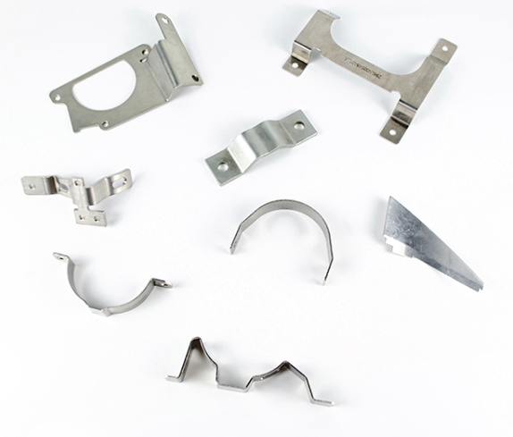
What Machining Process Creates ABS Prototypes?
Setting Up for ABS Machining
CNC machining remains the preferred method for ABS instrument prototypes because it delivers:
- Tolerance: ±0.05mm typical
- Surface finish: Ra 0.8-1.6μm as-machined
- No layer lines (unlike 3D printing)
- Material properties unchanged by process
Machine Selection:
- 3-axis CNC: For simple parts, flat geometries
- 4-axis CNC: For parts needing rotated features
- 5-axis CNC: For complex curves, angled features
- Multi-tasking machines: For complete parts in one setup
3-Axis vs 5-Axis: Making the Choice
| Factor | 3-Axis CNC | 5-Axis CNC |
|---|---|---|
| Best for | Simple brackets, flat panels | Complex housings, ergonomic shapes |
| Setup time | 1-2 hours | 2-4 hours |
| Multiple setups | Often needed for complex parts | Usually one setup completes part |
| Accuracy | Good | Excellent (no repositioning errors) |
| Cost per part | Lower for simple parts | Lower for complex parts overall |
| Example | ABS sensor mounting plate | ABS handheld analyzer casing |
Real Case: A US medical device company needed a ABS diagnostic instrument prototype with complex curves for comfortable grip. Using 5-axis machining, they completed the part in one day instead of three days with multiple 3-axis setups. The single setup also eliminated alignment errors between operations.
Real-Time Measurement During Machining
Don’t wait until the end to check dimensions:
In-Process Checks:
- Use probes to verify critical features
- Measure after roughing before finishing passes
- Check wall thickness with ultrasonic gauges
- Verify flatness before unclamping
Real Case: While machining a ABS liquid level sensor prototype, a manufacturer used in-process CMM measurements and found a 0.08mm deviation in the sensor mounting bore. They adjusted the tool offset for the finishing pass and saved the part. Without real-time measurement, they would have scrapped it after completion.
What Post-Processing Makes ABS Prototypes Production-Ready?
Mechanical Finishing Steps
Your ABS part comes off the CNC machine with visible tool marks. Here’s how to fix that:
Deburring Process:
- Remove obvious flashing with knife
- Sand with 220-grit for heavy marks
- Progress to 400-grit for smoothing
- Finish with 600-grit for paint-ready surface
- Wet sand for highest quality
A ABS control panel prototype typically needs 15-30 minutes of hand finishing to remove all machining marks, especially around button holes and display cutouts.
Surface Treatment Options
Different instruments need different finishes:
| Treatment | Best For | Process | Example Application |
|---|---|---|---|
| Priming/Painting | Color matching, branding | Spray primer + color coat | ABS medical device prototype in corporate colors |
| Silk screen | Labels, icons, scales | Screen ink onto surface | Measurement markings on ABS gauge prototype |
| Electroless plating | Conductivity, shielding | Chemical deposition | EMI shielding on ABS sensor housing |
| Texture coating | Grip, hiding fingerprints | Spray texture paint | Handheld ABS tester prototype |
| Clear coating | Protection, gloss | Spray clear lacquer | Display ABS demonstrator models |
Important: ABS accepts paint well, but always use primer designed for plastics. Some solvent-based paints can attack ABS and cause cracking. Water-based acrylics are generally safe.
Adding Functional Features
Sometimes post-processing adds function, not just appearance:
- Thread tapping: Add threads to machined holes for assembly
- Heat-set inserts: Install brass threads for repeated assembly
- Bonding: Assemble multi-part prototypes with ABS-compatible adhesives
- Overmolding simulation: Add silicone grips to simulate production feel
Real Case: A ABS portable oscilloscope prototype needed to feel like the production unit, which would have overmolded rubber grips. The prototyping team added self-adhesive silicone pads to the ABS casing—not identical to production but close enough for ergonomic testing.
How Do You Test ABS Prototypes Thoroughly?
Assembly Verification
Before functional testing, verify that everything fits and works together:
Assembly Checklist:
- All parts mate without excessive force
- PCBs fit in designated spaces
- Screws thread properly into bosses
- Batteries insert and contact correctly
- Cables route without pinching
- Buttons actuate without binding
- Display windows align with screens
A ABS multi-parameter water meter prototype might have 15-20 separate parts. Assembly testing ensures everything comes together correctly before you invest in functional testing.
Functional Testing Protocols
Now test how it performs:
For Measurement Instruments:
- Test accuracy against known standards
- Check repeatability across multiple readings
- Verify temperature compensation if applicable
- Example: ABS pH meter prototype tested in buffer solutions
For Handheld Devices:
- Check grip comfort with different users
- Test one-handed operation
- Verify button accessibility
- Example: ABS portable analyzer prototype used by 5 testers
For Environmental Exposure:
- Temperature cycling (if applicable)
- Humidity exposure
- Dust resistance (for IP-rated designs)
- Example: ABS outdoor sensor prototype in environmental chamber
For Mechanical Durability:
- Drop testing from specified heights
- Button life cycling (10,000+ presses)
- Cable flex testing
- Example: ABS industrial thermometer prototype drop-tested 20 times
Data Point: Industry analysis shows that 85% of successful instrument launches involved at least 2 full rounds of functional testing on prototypes. Products with insufficient testing have a 4x higher field failure rate in the first year.
What to Document During Testing
Keep detailed records:
Documentation Requirements:
- Photos before, during, and after each test
- Measurements at all critical points
- Pass/fail criteria and results
- Observations on unexpected behavior
- User feedback on ergonomics and usability
- Photos of any failures or issues
This documentation becomes critical when deciding whether to proceed to production or make another iteration.
How Do You Ensure Quality Control?
Implementing Multiple Checkpoints
Quality isn’t a final inspection—it’s built into every step:
Material Receiving:
- Verify ABS grade matches order
- Check material certificates
- Inspect for contamination or damage
In-Process Checks:
- First article inspection
- In-process dimensional verification
- Visual inspection after each operation
Final Inspection:
- Complete dimensional report
- Surface finish verification
- Functional check (if applicable)
- Packaging quality check
Following Industry Standards
Your ABS instrument prototype may need to meet specific standards:
| Standard | Applicability | Key Requirements |
|---|---|---|
| ISO 9001 | General quality | Documented processes, traceability |
| ISO 13485 | Medical instruments | Risk management, design controls |
| ISO/IEC 17025 | Testing labs | Measurement traceability |
| UL 94 | Flammability | Material certification |
| IP ratings | Environmental sealing | Gasket fit, seal integrity |
Real Case: A manufacturer developing a ABS medical diagnostic prototype needed ISO 13485 compliance for eventual production. They insisted their prototyping partner follow the same documentation standards—creating traceability from the first prototype. This decision saved 6 months during FDA submission because they had complete design history from day one.
How Can You Optimize Cost and Timeline?
Understanding Cost Drivers
| Cost Component | Typical Percentage | Optimization Strategy |
|---|---|---|
| Material | 10-15% | Use ABS where possible, specialty materials only where needed |
| Machining | 40-50% | Simplify designs, reduce deep cavities |
| Setup/Programming | 15-20% | Batch similar parts, reuse programs |
| Post-processing | 10-15% | Specify only necessary finishes |
| Quality/Inspection | 5-10% | In-process checks reduce final inspection time |
| Project management | 5-10% | Clear communication reduces revisions |
Timeline Expectations
Typical ABS Prototype Timeline:
- Design review and analysis: 1-2 days
- Programming and setup: 1-2 days
- Machining: 1-3 days (depending on complexity)
- Post-processing: 1-2 days
- Inspection: 0.5-1 day
- Shipping: 1-5 days (depending on location)
Total: 5-12 working days from approved design to delivered prototype.
Speed vs. Quality Trade-offs
Sometimes you need a prototype fast. Here’s what speeds up and what slows down:
Speed Accelerators:
- Simpler designs with fewer features
- Standard ABS grades (in stock)
- Fewer surface finish requirements
- Local shipping
- Overtime machining (additional cost)
Speed Reducers:
- Complex 5-axis work
- Multiple material types
- Extensive post-processing
- International shipping
- Multiple design revisions
Real Case: A client needed a ABS prototype for a trade show in 5 days. They accepted:
- Standard ABS (not the specialty grade they wanted)
- As-machined finish (no painting)
- Simple two-part design (consolidated features)
- Overnight shipping
The prototype wasn’t perfect, but it showed the concept at the show. They ordered a finished version later for actual testing.
Conclusion
ABS instrument prototype model proofing is a structured process that rewards attention to detail at every step. From selecting the right ABS grade to final quality inspection, each phase offers opportunities to improve your prototype and reduce development risk.
The key takeaways from this guide:
- Material selection matters—choose ABS grades that match your instrument’s functional needs
- Design analysis catches 70% of potential issues before you cut material
- CAM programming with proper simulation reduces machining errors by 65%
- CNC machining delivers precision and surface finish that 3D printing can’t match
- Post-processing transforms machined parts into production-representative samples
- Functional testing with documentation ensures design issues are caught early
- Quality control with traceability prepares you for production compliance
Remember that successful prototyping isn’t about perfection on the first try. It’s about learning fast, making targeted improvements, and moving closer to a production-ready design with each iteration. ABS’s unique combination of properties makes it the ideal material for this journey—tough enough for repeated testing, machinable enough for quick iterations, and cost-effective enough for multiple design cycles.
Whether you’re developing the next generation of industrial sensors or refining a laboratory analyzer, following this process will help you create prototypes that actually predict production performance—saving time, money, and surprises when you finally go to market.
Frequently Asked Questions
Q: How long does ABS instrument prototype proofing take from start to finish?
A: Typical timeline is 7-12 working days. Simple parts (like ABS sensor brackets) take 5-7 days. Complex prototypes (like curved ABS instrument casings with multiple features) take 10-12 days including post-processing and shipping.
Q: Can I get an ABS prototype that matches my production color exactly?
A: Yes—through painting with color-matched paint. Provide a RAL number, Pantone reference, or physical sample. Most prototyping services can match within ΔE < 1.0 tolerance.
Q: How many ABS prototypes should I order for a typical instrument development project?
A: Order 3-5 units minimum. This allows for assembly testing, destructive testing of one unit (like drop tests), and spare parts for unexpected needs. For complex instruments, 8-10 units give better statistical confidence.
Q: Will my ABS prototype have the same strength as injection-molded production parts?
A: Very close—within 90-95% of molded strength. The main difference is that machined ABS lacks the molecular orientation of molded parts, but for most functional tests, this difference isn’t significant. Impact resistance may be slightly lower in machined parts.
Q: What’s the minimum wall thickness for ABS prototypes?
A: 1.2mm for small parts, 1.5mm for medium parts, 2.0mm for larger components. Thinner walls (down to 0.8mm) are possible but require careful machining and risk breakage during handling. Production injection molding may allow thinner walls.
Q: Can I modify an ABS prototype after it’s made?
A: Yes—ABS machines well after initial production. You can drill holes, sand surfaces, bond parts, and paint. Use ABS-compatible adhesives (like solvent cements or cyanoacrylates) for strong bonds. Heat-based modifications can cause melting.
Q: Is ABS more cost-effective than other materials for instrument prototypes?
A: Yes—ABS costs about 30-40% less than PC and 50-60% less than specialty engineering plastics. It’s ideal for prototypes where extreme heat resistance (>95°C) or optical clarity aren’t needed. For most room-temperature instruments, ABS is the most cost-effective choice.
Q: What surface finish can I expect on machined ABS prototypes?
A: As-machined ABS has a matte finish with visible tool marks (Ra 0.8-1.6μm). Sanding can achieve a smooth matte finish. With proper priming and painting, you can achieve gloss levels from 10-90 units (gloss meter reading), matching production finishes.
Discuss Your Projects with Yigu Rapid Prototyping
At Yigu Rapid Prototyping, we’ve supported over 400 instrumentation brands with ABS instrument prototype model proofing. Our approach combines technical precision with practical efficiency:
- Multi-axis CNC capabilities for complex ABS parts—from simple brackets to intricate handheld enclosures
- Material expertise across ABS grades, blends, and complementary materials
- ISO 9001 quality systems with full traceability for regulated industries
- Design analysis support to catch issues before they cost you time
- Flexible finishing options from as-machined to production-matched painting
We start every instrumentation project with a design review—identifying potential manufacturing issues before they become problems. For medical device clients, we follow documentation practices that support regulatory submissions. For time-critical projects, we offer accelerated machining options without compromising quality.
Whether you’re prototyping a new industrial sensor, refining a laboratory analyzer, or testing a handheld diagnostic device, we’re ready to help. Contact Yigu Rapid Prototyping to discuss your specific ABS prototype needs. Send us your CAD files for a free quote and feasibility analysis within 24 hours. Let’s turn your instrument design into a functional prototype that accelerates your path to market.