Power prototype machining refers to the specialized manufacturing processes used to create physical prototypes of power modules (НАПРИМЕР., chargers, adapters, lithium battery protection boards). These processes validate design feasibility, структурная стабильность, and functional performance—critical for reducing risks in electronic product development. Unlike general prototype machining, power prototype machining prioritizes precision for heat dissipation, component compatibility, and safety compliance (НАПРИМЕР., voltage insulation). This article breaks down its core machining methods, пошаговые рабочие процессы, выбор материала, Поиск неисправностей, and real-world applications to guide teams toward successful prototype creation.
1. What Are the Core Machining Methods for Power Prototypes?
Each method is tailored to specific power prototype needs—from complex shell shapes to high-precision metal components. The table below compares their key traits, приложения, and advantages.
| Метод обработки | Основные характеристики | Пошаговый рабочий процесс | Applicable Power Prototype Types | Ключевые преимущества |
| 3D Printing Machining | – Layer-by-layer deposition of plastic/resin.- Поддержка Полые структуры и complex curves (НАПРИМЕР., custom charger shells).- Материалы: Плата (бюджетный), АБС (Высокая сила), смола (высокая точность). | 1. Use SolidWorks/UG to design the power enclosure (include heat dissipation holes, interface cutouts).2. Экспортируйте модель как файл STL; use slicing software (Уход) to set parameters: – Высота слоя: 0.1–0,2 мм (higher precision for resin). – Наполнять: 20–30% (structural stability without excess weight). – Поддержка: Add for overhangs (НАПРИМЕР., USB-C interface lips).3. Print with FDM (ПЛА/АБС) или sla (смола).4. Post-process: Удалить опоры, sand with 200→800 grit sandpaper, and polish resin parts for smoothness. | – Consumer power supplies (portable chargers, phone adapters).- Customized power housings (non-standard shapes for IoT devices).- Маленькие прототипы (1–10 units for design verification). | – Rapid turnaround (4–24 hours per prototype).- Low upfront cost (no mold required).- Ideal for iterative design (easy to modify and reprint). |
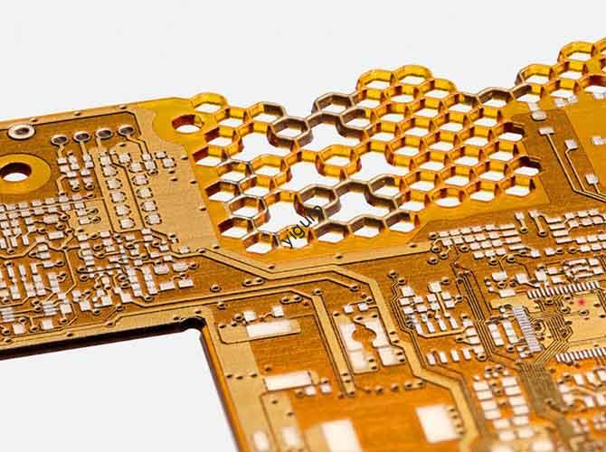
| Обработка с ЧПУ | – Computer-controlled cutting of solid materials (metal/plastic).- Ультра-высокая точность (терпимость: ± 0,05 мм) для heat dissipation modules и metal enclosures. | 1. Convert 3D models to G-code using CAM software (Мастеркам).2. Secure the material block (алюминиевый сплав, Пома, акрил) to the CNC machine bed.3. Установите параметры резки: – Скорость шпинделя: 10,000–15,000 RPM (higher for metal, lower for plastic). – Скорость корма: 500–1000mm/min (adjust to avoid material melting). – Глубина резания: 0.1–0,5 мм за проход (prevents tool breakage).4. Machine the part (drill holes, carve shells, mill heat dissipation fins).5. Post-process: Deburr with a file, sandblast aluminum parts for texture, and polish acrylic for transparency. | – Industrial power supplies (high-power modules for factories).- Metal enclosures (aluminum alloy chargers for outdoor use).- Точные компоненты (радиаторы, PCBA mounting brackets). | – Superior structural strength (suitable for load-bearing parts).- Превосходное качество поверхности (supports plating, Анодирование).- Matches mass production material properties (critical for functional testing). |
| Silicone Duplicate Machining | – Mold-based replication using a master prototype (3D-printed/CNC-machined).- Cost-effective for soft shells и Маленькая партийная производство (10–50 единиц). | 1. Создать мастер -прототип (НАПРИМЕР., 3D-printed resin power shell).2. Build a mold box around the master; pour liquid silicone (viscosity 500–2000 cP) and add vent holes to release air.3. Cure the silicone mold at 25–80°C for 4–24 hours.4. Demold the master; inject PU resin, эпоксидная смола, or silicone into the mold.5. Cure the replicated part, then trim excess material (следы ворот) and sand edges. | – Soft power grips (rubberized handles for industrial chargers).- Flexible enclosures (waterproof power modules for outdoor gear).- Low-cost trials (validating design before CNC/3D printing large batches). | – Low per-unit cost (\(3- )15 за часть).- Preserves master details (НАПРИМЕР., texture on silicone grips).- Fast replication (3–5 days per batch). |
2. What Is the Step-by-Step Design & Machining Workflow for Power Prototypes?
The workflow integrates design validation, обработка, and testing to ensure the prototype meets electronic product standards.
2.1 Шаг 1: Подготовка дизайна (Заложить фундамент)
Design decisions directly impact machining feasibility and power performance.
| Design Stage | Key Tasks | Power-Specific Considerations |
| ID Design | Define the power supply’s shape (cuboid, цилиндрический), interface type (USB-C, DC port), heat dissipation hole layout, and indicator light position. | – Отверстия для отвода тепла: Use mesh patterns (≥1mm diameter) to prevent dust accumulation while maximizing airflow.- Interface placement: Ensure USB ports are centered and aligned with internal PCBA connectors (avoid misalignment during assembly). |
| MD Design | Design internal structures: battery compartment size, PCBA fixed positions (screw holes, snap fits), and draft angles (≥1° for CNC-machined plastic parts). | – Screw hole placement: Space holes 20–30mm apart for even PCBA support.- Проект углов: Critical for CNC machining—prevents parts from sticking to cutting tools and reduces post-processing time. |
| DFMEA Analysis | Evaluate potential risks: assembly gaps, insufficient heat dissipation, electromagnetic interference (EMI), and short-circuit hazards. | – Heat dissipation: Simulate temperature distribution (используйте программное обеспечение, такое как ANSYS) чтобы ни один компонент не превышал 85°C. (стандарт для силовых модулей).- защита от электромагнитных помех: Спроектируйте экранирующие отсеки для трансформаторов, чтобы избежать помех расположенной поблизости электронике.. |
2.2 Шаг 2: Обработка выполнения (Produce the Prototype)
Выберите метод в зависимости от цели прототипа. (внешний вид против. функция) и размер партии.
| Сценарий | Рекомендуемый метод обработки | Обоснование | Пример |
| Проверка внешнего вида (1–5 единицы) | 3D Печать (Смола) | Быстрый, захватывает мелкие детали (НАПРИМЕР., этикетки с шелкографией по напряжению), бюджетный. | Прототип зарядного устройства для телефона мощностью 20 Вт из смолы для проверки формы корпуса и расположения кнопок.. |
| Функциональное тестирование (5–20 единиц) | Обработка с ЧПУ (Алюминиевый сплав/ПОМ) | Высокая точность, прочный для повторных испытаний (НАПРИМЕР., подключение/отключение кабелей). | Алюминиевый прототип платы защиты литиевой батареи, обработанный на станке с ЧПУ, для проверки стабильности выходного напряжения.. |
| Мелкосерийное испытание (20–50 единиц) | Силиконовый дубликат (PU Strain) | Low per-unit cost, копирует основные детали (НАПРИМЕР., ребра теплоотвода). | 30 Прототипы модуля питания IoT-устройства из полиуретановой смолы для отзывов клиентов. |
2.3 Шаг 3: Поверхностная обработка (Повысить производительность & Эстетика)
Обработка поверхности повышает долговечность, безопасность, и пользовательский опыт, что критически важно для мощных прототипов.
| Тип лечения | Цель | Энергозависимые приложения | Метод |
| Распыление | – Покрытие против отпечатков пальцев.- Электрическая изоляция (для пластиковых корпусов). | – Черный матовый спрей для зарядных устройств (скрывает царапины).- Изоляционная краска для корпусов печатных плат. (prevents electric shock). | Нанесите 2–3 тонких слоя (drying time: 30 minutes per coat); отверждение при 60°C для 1 час. |
| Покрытие | – Коррозионная стойкость (для металлических деталей).- Проводимость (for grounding components). | – Anodizing aluminum alloy heat sinks (prevents rust and improves heat transfer).- Nickel plating on copper connectors (reduces oxidation). | Use electrolytic plating; control thickness (5–10μm for corrosion resistance). |
| Texture Treatment | – Anti-slip grip.- Brand identification. | – Laser-engraved patterns on charger sides (improves handling).- Silk-screened logos/parameters (input: 100–240V, выход: 5V/2A). | Лазерная гравировка (глубина: 0.1–0,2 мм) for textures; silk screening with high-adhesion ink (cure at 80°C). |
2.4 Шаг 4: Сборка & Функциональное тестирование (Validate Reliability)
Power prototypes require rigorous testing to ensure safety and performance.
2.4.1 Процесс сборки
- Component Preparation: Gather PCBA boards, Трансформеры, радиаторы, cables, and screws (M2–M3 for small power supplies).
- Secure Internal Parts:
- Mount the PCBA to the enclosure using screws or snap fits (ensure no contact with metal parts to avoid short circuits).
- Attach heat sinks with thermal paste (толщина: 0.1мм) to high-temperature components (НАПРИМЕР., voltage regulators).
- Interface Installation: Insert USB-C/DC ports into the shell; solder cables to the PCBA (ensure solid connections to prevent voltage drops).
2.4.2 Critical Tests for Power Prototypes
| Тип теста | Метод | Acceptance Standard |
| Electrical Performance | Use a multimeter to measure voltage/current output; simulate overload (120% of rated current) and short circuits. | – Voltage output: ±5% of rated value (НАПРИМЕР., 5V ±0.25V for a 5V charger).- Overload protection: Shuts down within 1 second and reboots safely. |
| Heat Dissipation | Operate the power supply at full load for 2 часы; use an infrared thermometer to measure component temperatures. | – No component exceeds 85°C (critical for lithium battery protection boards).- Enclosure surface temperature ≤45°C (safe for user touch). |
| Структурная долговечность | Simulate 1000 cycles of plugging/unplugging cables; drop the prototype from 1m onto a hard surface. | – No loose components or cable detachment after testing.- Shell remains intact (no cracks that expose internal circuits). |
3. What Are the Best Practices for Power Prototype Machining?
3.1 Material Selection for Power-Specific Needs
Choose materials based on heat resistance, изоляция, and structural requirements:
| Материал | Ключевые свойства | Ideal Power Prototype Components |
| Алюминиевый сплав (6061) | Легкий вес, Высокая теплопроводность (167 W/m · k), коррозионная устойчивость. | Радиаторы, metal enclosures for high-power modules. |
| ABS Пластик | Хорошее воздействие сопротивления, теплостойкость (до 90 ° C.), Легко в машине. | Consumer charger shells, PCBA mounting brackets. |
| Пома (Полиоксиметилен) | Износостойкий, self-lubricating, низкое трение. | Movable parts (folding charger hinges, sliding cable covers). |
| Силикон | Мягкий, non-slip, температурная стойкость (-50° C до 200 ° C.). | Sealing rings (waterproof power modules), grip covers. |
| Смола (СЛА) | Высокая точность, гладкая поверхность, электрическая изоляция. | Внешний вид прототипов (clear enclosures for LED indicator lights). |
3.2 Precision Control for Safety & Производительность
- Heat Dissipation Holes: Ensure hole diameter is ≥1mm (prevents clogging) and spacing is 5–10mm (maximizes airflow). Use CNC machining for uniform hole placement (avoids 3D printing’s layer-line blockages).
- Screw Holes: Align holes with PCBA mounting points (терпимость: ± 0,1 мм) to prevent component stress. Use CNC drilling for consistent depth (avoids over-drilling that damages internal circuits).
- Interface Cutouts: For USB-C/DC ports, machine cutouts with a 0.1mm clearance around the connector (обеспечивает легкую установку без помех).
3.3 Troubleshooting Common Machining Issues
| Проблема | Первопричина | Решение |
| 3Корпус с D-печатью деформируется во время охлаждения | Материал PLA дает усадку (1.5–2%) после печати; неравномерное охлаждение. | – Используйте теплую кровать (60° C для PLA) во время печати.- Закройте принтер, чтобы поддерживать постоянную температуру.- Спроектировать оболочку с ребрами жесткости. (1–2 мм толщиной) Чтобы уменьшить деформацию. |
| Алюминий, обработанный на станке с ЧПУ, имеет заусенцы на ребрах радиатора | Режущий инструмент затупился; скорость подачи слишком высокая. | – Замените инструмент заточенной твердосплавной концевой фрезой.- Уменьшите скорость подачи на 20% (НАПРИМЕР., от 1000 мм/мин до 800 мм/мин).- Используйте диск для снятия заусенцев, чтобы сгладить края ребер после обработки.. |
| Silicone-Duplicated Parts Have Air Bubbles | Silicone mold has no vent holes; resin injected too quickly. | – Add 1–2mm diameter vent holes to the mold’s highest points.- Inject resin slowly (1–2ml/s) to let air escape.- Tap the mold gently during injection to release trapped bubbles. |
Перспектива Yigu Technology
В Yigu Technology, we see power prototype machining as a “safety-first engineering process”—it’s not just about making a physical model, but validating the reliability of a product that handles electricity. Too many clients overlook power-specific needs (НАПРИМЕР., heat dissipation, изоляция) and use general machining methods, leading to prototypes that fail functional tests. Наш подход: We prioritize material-process matching—e.g., using CNC-machined aluminum for heat sinks (not 3D-printed PLA, which melts at high temperatures) and silicone duplication for soft grips (not CNC plastic, which lacks flexibility). Например, we helped a client fix a charger prototype’s overheating issue by machining aluminum heat dissipation fins (replacing a 3D-printed plastic shell), cutting component temperatures by 30%. Сосредоточив внимание на требованиях к электропитанию, мы помогаем клиентам избежать дорогостоящих переделок и обеспечить соответствие их прототипов стандартам безопасности массового производства.
Часто задаваемые вопросы
- Могу ли я использовать 3D-печать для создания мощного прототипа? (НАПРИМЕР., 60W промышленный модуль)?
3D-печать подходит для проверки внешнего вида, но не для функциональных прототипов высокой мощности. Высокая мощность генерирует тепло (≥80°С) который может расплавить PLA/ABS. Для функционального тестирования, использовать алюминиевый сплав, обработанный на станке с ЧПУ (для рассеяния тепла) или ПОМ (термостойкий пластик) чтобы гарантировать, что прототип выдерживает рабочие температуры.
- How long does power prototype machining take for a 5V/2A charger?
Это зависит от метода: 3D printing takes 8–12 hours (в том числе после обработки); CNC machining takes 1–2 days (material setup + резка); дублирование силикона занимает 3–5 дней (Создание формы + replication). Add 1–2 days for assembly and testing.
- What’s the most cost-effective method for 20 units of a custom power enclosure?
Лучше всего использовать силиконовое дублирование.. Make a single 3D-printed master prototype (\(20- )50), then produce 20 PU resin copies (\(3- )15 каждый) — total cost (\(80- )225) является 50% cheaper than CNC machining 20 separate units (\(150- )400).