А CNC machining air conditioning prototype process is a systematic workflow that transforms air conditioning design concepts into physical prototypes, проверка подлинности внешнего вида, structural rationality, heat exchange efficiency, и основная функциональная логика (НАПРИМЕР., airflow uniformity, noise control). В этой статье поэтапно разбивается процесс — от предварительного проектирования до окончательной отладки — с использованием таблиц, управляемых данными., практические рекомендации, и советы по устранению неполадок, которые помогут вам справиться с ключевыми проблемами и обеспечить успех прототипа..
1. Предварительная подготовка: Define Requirements & Lay the Design Foundation
Preliminary preparation sets the direction for the entire prototype development. Он ориентирован на две основные задачи: requirements analysis & conceptual design и 3D Моделирование & structural detailing, both tailored to the unique needs of different air conditioning types (НАПРИМЕР., compact structure for wall-mounted AC, multi-directional airflow for central AC).
1.1 Анализ требований & Conceptual Design
Before starting machining, clarify functional and appearance requirements to avoid misaligned development goals—this step reduces rework risk by 30% в среднем.
1.1.1 Functional Requirements Clarification
Different AC types have distinct functional priorities. The table below outlines key specs for common models:
| AC Type | Основная функциональная направленность | Пример ключевых характеристик |
| Wall-Mounted AC | Compact indoor unit, efficient heat exchange | Cooling capacity: 2–3.5kW; Шум (indoor unit): ≤30dB; Indoor unit thickness ≤180mm |
| Vertical AC | Large airflow, stable base | Cooling capacity: 3.5–5kW; Air supply range: 0°–90° (up/down swing); Base weight ≥30kg |
| Central AC Outlet | Multi-directional airflow, совместимость | Airflow uniformity: ±5% variation; Swing angle (слева/справа): 0°–120°; Material corrosion resistance |
1.1.2 Внешний вид Концептуальный дизайн
Создавайте предварительные эскизы или 3D-чертежи, используя такие инструменты, как Эскиз или Носорог, with three key considerations:
- Эстетическая координация: Wall-mounted ACs use slim, curved lines (radius 8–12mm) to fit home walls; vertical ACs adopt cylindrical or rectangular shapes for living room decor.
- Взаимодействие человека и компьютера: Place displays and buttons at eye level (1.5–1.8m from the ground for wall-mounted ACs); use touch-sensitive or physical knobs with clear icons.
- Environmental Adaptation: Add dust filters (removable design for easy cleaning) and drainage ports (positioned to avoid water leakage); use anti-mildew materials for high-humidity areas.
1.2 3D Моделирование & Structural Detailing
Use professional CAD software to translate concepts into precise models, ensuring processability for CNC machining.
1.2.1 Выбор программного обеспечения & Core Structural Design
- Выбор программного обеспечения: Расставить приоритеты Солидворкс, И nx, или Для/e— они поддерживают параметрическое проектирование, allowing easy adjustment of dimensions (НАПРИМЕР., evaporator size, air duct width) and compatibility with CAM software.
- Разбивка компонентов: Split the AC into parts like indoor/outdoor unit housing, Компоненты воздушного воздуховода (deflectors, volutes), радиаторы, motor brackets, и управляющие панели for separate machining.
- Key Structure Optimization:
- Жилье: Determine material thickness (1–3mm for plastic, 0.8–1.5mm for aluminum alloy) and assembly structures (снимки, M3–M4 screw holes with ±0.1mm tolerance).
- Air Ducts: For wall-mounted ACs, optimize airflow paths to reduce turbulence (НАПРИМЕР., curved volutes with 5°–10° expansion angle); for central AC outlets, design multi-layer deflectors for uniform air distribution.
- Heat Sinks: Design fin density (0.5–1mm spacing) и форма (wavy or louvered) based on heat exchange efficiency—wavy fins improve heat dissipation by 15% compared to flat fins.
- Detail Features: Add brand logos (embossed height 0.8–1mm), indicator light holes (диаметр 3–5 мм), and filter mounting grooves (depth 5–8mm, Допуск ± 0,05 мм).
2. Выбор материала & Планирование процессов: Match Materials to Performance Needs
Choosing the right materials and defining machining strategies are critical for prototype performance. This phase follows a “material selection → parameter setting → sequence planning” workflow to ensure efficiency and precision.
2.1 Выбор материала: Balance Performance, Расходы, and Processability
Different AC components require materials with specific properties (НАПРИМЕР., thermal conductivity for heat sinks, corrosion resistance for outdoor units). The table below compares suitable options:
| Компонент | Рекомендуемый материал | Ключевые свойства | Преимущества обработки | Диапазон затрат (за кг) |
| Indoor Unit Housing | ABS Пластик / ПК Смесь | Легкий вес, воздействие, low noise transmission | Легко разрезать; smooth surface for painting | \(3- )6 |
| Outdoor Unit Housing | Алюминиевый сплав (6061) / Нержавеющая сталь (304) | Коррозионная устойчивость, долговечный, Погода | Good for anodization; high strength for outdoor use | \(6- )10 (Алюминий); \(15- )22 (SS) |
| Air Duct Components | ABS Пластик / Алюминиевый сплав | Высокая жесткость, Хорошая стабильность | Пластик: No burrs; Металл: Suitable for curved machining | \(3- )6 (Пластик); \(6- )10 (Металл) |
| Heat Sinks | Алюминиевый сплав (1050) / Медь | Отличная теплопроводность (Ал: 220 W/m · k; Кузок: 401 W/m · k) | Fast machining; easy to form fins | \(5- )8 (Алюминий); \(18- )25 (Медь) |
| Control Panels | АБС + ПК Смесь | Изоляция, воздействие сопротивления, smooth surface for silk-screen | Compatible with touch-sensitive film installation | \(4- )7 |
Пример: Wall-mounted AC heat sinks use aluminum alloy (рентабельный, легкий вес), while high-end central AC heat sinks use copper (superior thermal conductivity) for large cooling capacity.
2.2 Планирование процессов: Define CNC Machining Strategies
Clear process planning ensures efficient and precise machining, сокращение времени производства 20%.
2.2.1 Tool Selection by Material & Задача
| Материал | Задача обработки | Тип инструмента | Спецификации |
| Пластик (ABS/PC) | Грубая | Carbide Flat-End Mill | Φ6–10mm, 2–3 зуба |
| Пластик (ABS/PC) | Отделка | Carbide Ball-Nose Mill | Φ2–4mm, 4–6 зубов |
| Алюминиевый сплав | Грубая | Carbide End Mill | Φ4–6mm, 2 зубы |
| Алюминиевый сплав | Отделка | TiAlN-Coated Carbide Cutter | Φ3–5mm, 4 зубы |
| Нержавеющая сталь | Грубая | High-Speed Steel End Mill | Φ4–8mm, 2 зубы |
| Нержавеющая сталь | Отделка | Diamond-Coated Cutter | Φ2–4mm, 4 зубы |
2.2.2 Настройка параметров резки
Оптимизированные параметры предотвращают деформацию материала и обеспечивают качество поверхности.:
| Материал | Стадия обработки | Скорость (об/мин) | Скорость корма (мм/зуб) | Глубина резки (мм) | Охлаждающая жидкость |
| ABS Пластик | Грубая | 300–600 | 0.2–0,5 | 0.5–2 | Сжатый воздух |
| ABS Пластик | Отделка | 800–1500 | 0.1–0,2 | 0.1–0,3 | Сжатый воздух |
| Алюминиевый сплав (6061) | Грубая | 1500–2500 | 0.1–0,3 | 1–3 | Эмульсия |
| Алюминиевый сплав (6061) | Отделка | 2500–4000 | 0.05–0,1 | 0.05–0,1 | Эмульсия |
| Нержавеющая сталь (304) | Грубая | 800–1200 | 0.08–0,15 | 0.3–1 | Эмульсия |
| Нержавеющая сталь (304) | Отделка | 1500–2000 | 0.03–0,08 | 0.03–0,05 | Эмульсия |
2.2.3 Machining Sequence
Следуйте этому порядку, чтобы избежать повреждения компонентов и обеспечить точность.:
- Сначала обрабатывайте крупные детали (НАПРИМЕР., внутренние/наружные корпуса) чтобы установить ссылку на сборку.
- Обработка сложных криволинейных поверхностей (НАПРИМЕР., volutes, deflectors) слоями (0.5–1 мм на слой) для обеспечения точности формы.
- Обработка мелких прецизионных деталей (НАПРИМЕР., motor brackets, Кнопки панели управления) последний, чтобы предотвратить столкновение.
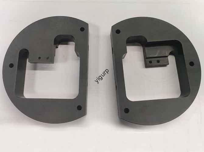
3. Исполнение обработки с ЧПУ: Turn Models into Physical Components
Этот этап является основой создания прототипа., после “machine preparation → roughing → semi-finishing → finishing” workflow to ensure component precision (tolerance ±0.03mm for key parts).
3.1 Machine Preparation & Программирование
- Machine Selection:
- Most parts (корпусы, радиаторы) Используйте 3-axis CNC milling machine (точность позиционирования ±0,01 мм).
- Complex parts like volutes or central AC deflectors require a 5-axis CNC machine for multi-angle machining.
- Программирование & Калибровка:
- Import 3D models into CAM software (НАПРИМЕР., Мастеркам, И nx) to generate toolpaths; set safety planes (5–10mm above the workpiece) to avoid tool collision.
- Clamp materials (plastic plates, aluminum blocks) and calibrate the zero point using a touch probe (accuracy ±0.005mm).
3.2 Грубая & Полуфинизируя: Shape the Basic Form
- Грубая: Remove 80–90% of excess material to approach the component’s basic shape. Например:
- Жилье: Mill the outer contour first, then dig the internal cavity (avoids plastic collapse).
- Heat Sinks: Rough-cut the base shape, leaving 0.5–1mm allowance for fin machining.
- Полуфинизируя: Correct roughing deviations and leave a 0.1–0.2mm allowance for finishing. Ключевые шаги включают в себя:
- Smoothing air duct inner walls to reduce airflow resistance.
- Pre-drilling screw holes (90% of final diameter) for precise tapping later.
3.3 Отделка: Достичь точности & Качество поверхности
Finishing determines the prototype’s appearance and functional performance. The table below outlines requirements for key components:
| Компонент | Шероховатость поверхности | Метод обработки |
| Indoor Unit Housing | Ра ≤0,8 мкм | Polish with 800–1200 mesh sandpaper; удалить следы инструмента |
| Heat Sinks | Ra ≤0.4μm | High-speed finishing for fin spacing (0.5–1 мм); deburr fin edges with a wire brush |
| Volutes | Ra ≤0.6μm | 5-axis finishing for curved surfaces; ensure smooth airflow path |
| Панель управления | Ра ≤1,6 мкм | Polish and clean; prepare for silk-screen or touch-sensitive film |
- Special Structure Machining:
- Heat sink fins: Use a specialized fin cutter to ensure uniform spacing (±0.05mm variation).
- AC outlet deflectors: Machine swing shafts with tolerance ±0.02mm to ensure smooth movement.
4. Пост-обработка & Сборка: Повысить производительность & Эстетика
Постобработка устраняет дефекты и подготавливает детали к сборке., while careful assembly ensures the prototype functions as intended.
4.1 Пост-обработка: Improve Durability & Появление
- Выслушивание & Уборка:
- Пластиковые детали: Use a blade to remove burrs; clean with isopropyl alcohol to eliminate oil residue.
- Металлические детали: Sand with 400–800 mesh sandpaper; для алюминия, use a wire brush to remove oxidation.
- Поверхностная обработка:
| Компонент | Метод лечения | Цель |
| Indoor Unit Housing | Spray matte/glossy paint; hot-stamp brand logos | Улучшить эстетику; prevent scratches |
| Outdoor Unit Housing | Анодировать (алюминий) or electroplate (нержавеющая сталь); add anti-UV coating | Улучшить коррозионную стойкость; withstand outdoor weather |
| Панель управления | Silk-screen buttons/icons; spray insulating paint | Ensure visibility; prevent electrical leakage |
- Functional Enhancement:
- Attach rubber seals to filter mounting grooves (improves air tightness by 20%).
- Install waterproof membranes on control panels to prevent dust/water ingress.
4.2 Сборка & Отладка: Проверка функциональности
Follow a sequential assembly order to avoid rework, then conduct comprehensive testing:
4.2.1 Assembly Sequence
- Assemble core components: Mount the evaporator/condenser to the housing → install the fan and motor → attach air duct components.
- Add secondary parts: Install the control panel → attach the filter → connect wires (use heat-shrinkable tubes for insulation).
- Secure structures: Use screws (крутящий момент: 1.5–2.0 N·m for M3 screws), снимки, or epoxy glue (for air duct joints).
4.2.2 Функциональная отладка
| Тестовый предмет | Инструменты/Методы | Критерии прохождения |
| Airflow Uniformity | Anemometer (measured at 1m from the outlet) | Variation ≤5% across different points; meets design airflow rate (НАПРИМЕР., 300m³/h for wall-mounted AC) |
| Noise Level | Sound level meter (indoor unit: 1m away; outdoor unit: 3m away) | Indoor unit ≤30dB; outdoor unit ≤55dB |
| Heat Exchange Efficiency | Thermometer (measure inlet/outlet air temperature) | Охлаждение: Temperature drop ≥8°C (в помещении); Обогрев: Temperature rise ≥5°C (в помещении) |
| Water Leakage | Fill drainage port with water (1Л); observe for 30 минуты | No leakage from housing or joints |
| Swing Function | Protractor + секундомер | Swing angle meets design specs (НАПРИМЕР., 0°–90° for wall-mounted AC); no jitter |
5. Случаи применения: Tailor Processes to AC Types
Different AC types require adjusted processes to meet their unique needs.
5.1 Wall-Mounted AC Prototype
- Фокус: Compact structure and silent operation.
- Process Adjustments:
- Use thin aluminum alloy (0.8мм) for the indoor unit housing to reduce thickness (≤180mm).
- Optimize air duct curvature to reduce turbulence (noise ≤30dB); test filter removal/installation ease.
5.2 Central AC Outlet Prototype
- Фокус: Multi-directional airflow and corrosion resistance.
- Process Adjustments:
- Используйте из нержавеющей стали (304) for outdoor-facing parts (коррозионная стойкость); machine deflectors with 5-axis CNC for 0°–120° swing.
- Test compatibility with central AC main units (airflow matching, installation fit).
Перспектива Yigu Technology
В Yigu Technology, Мы видим CNC machining air conditioning prototype process как “performance validator”—it identifies design flaws early to save mass production costs. Наша команда уделяет приоритетное внимание двум направлениям: precision and functionality. For key parts like heat sinks, we use aluminum alloy with 5-axis finishing (fin spacing ±0.05mm) to ensure heat exchange efficiency. For air ducts, we optimize curvature via CFD simulation and CNC machining (Ra ≤0.6μm) to reduce noise. Мы также интегрируем постобработку 3D-сканирования для проверки точности размеров. (± 0,03 мм), сокращение темпов доработок за счет 25%. Сосредоточив внимание на этих деталях, мы помогаем клиентам сократить время выхода на рынок на 1–2 недели. Whether you need a wall-mounted or central AC prototype, we tailor solutions to meet global energy efficiency and safety standards.
Часто задаваемые вопросы
- Q.: How long does the entire CNC machining air conditioning prototype process take?
А: Typically 12–18 working days. This includes 2–3 days for preparation (requirements analysis, моделирование), 4–6 дней для обработки ЧПУ, 2–3 дней для постобработки, 3–4 days for assembly, and 1–2 days for debugging/testing.