Introduction
You have a carefully designed digital plan. The next important step is changing that idea from images on a screen into a real, working metal part that you can hold, тест, and check. This is the main challenge of making products, and prototype sheet metal fabrication is the answer. This guide walks you through the complete process from start to finish, from making your computer design ready for manufacturing to understanding the final touches that make a part ready for production.
Getting the prototype phase right is not just about making one part; it’s about setting up the entire project for success. A well-made functional prototype lets you test shape, соответствовать, и сборка, find design problems early, and create a production-intent part that makes the move to mass production smoother. Putting effort into thoughtful design and fabrication early on is the best way to save lots of time and money later.
—
An Overview of Sheet Metal Prototyping
What is Prototype Sheet Metal Fabrication?
Prototype sheet metal fabrication is the manufacturing process of making small amounts or single parts from flat metal sheets to test, check, and improve a design. В отличие от массового производства, which uses expensive, permanent tools like stamping dies, prototyping uses flexible, tool-less, or low-cost tool methods. This approach focuses on speed and adaptability, letting engineers quickly get physical parts in their hands. The main goal is to check the three pillars of a successful design: *form* (does it look right?), *fit* (does it fit correctly with other parts?), and *function* (does it do its intended job under real-world conditions?).
The Important Role of Prototyping in Product Development
A physical prototype is the bridge between theory and reality. It’s the first chance to prove that your design works outside of the controlled environment of a computer program. Having a strong prototyping phase gives several key advantages that reduce risk for your entire project.
- Проверка дизайна: There is no substitute for a physical part. You can test clearances, check mounting points, verify comfort, and ensure smooth assembly with matching parts long before spending money on expensive production tools.
- Функциональное тестирование: A metal prototype lets you put your design through real-world stresses, loads, и условия окружающей среды. Does the bracket hold the required weight? Does the case get rid of heat effectively? Prototyping answers these questions.
- Снижение риска: Finding a design flaw after production tools have been made is an expensive and time-consuming disaster. Prototyping lets you identify and fix these errors early when changes are still just a simple computer adjustment.
- Faster Improvement: The speed of modern prototyping lets you quickly move from one design version to the next. This rapid feedback loop helps you refine your product faster, innovate more effectively, and get to market ahead of competitors.
Common Materials Used in Sheet Metal Prototyping
Choosing the right material is an important early decision that affects cost, производительность, and how easy it is to manufacture. While we can work with many different alloys, most prototypes are built from a few common, универсальный, and cost-effective metals.
| Материал | Ключевые характеристики | Common Prototype Applications |
| Алюминий (НАПРИМЕР., 5052, 6061) | Легкий вес, ржавчатый, Хорошее соотношение силы к весу. | Случаи, скобки, рамы, аэрокосмические части. |
| Сталь (НАПРИМЕР., Холод катился, Оцинкован) | Сильный, долговечный, рентабельный. | Структурные части, рамы, industrial hardware. |
| Нержавеющая сталь (НАПРИМЕР., 304, 316) | Высокая сила, excellent rust/heat resistance, attractive finish. | Медицинские устройства, food-grade equipment, Морские части. |
| Copper/Brass | Excellent electrical/heat conductivity, Сопротивление ржавчины. | Автобусы, разъемы, радиаторы, декоративные детали. |
—
Mastering Design for Manufacturability (DFM)
Дизайн для производства (DFM) is the practice of designing parts in a way that makes them easy and efficient to manufacture. It’s the single most important factor you can control to reduce cost, shorten lead times, and improve the quality of your prototype. As your fabrication partner, we see DFM as a team process. By building manufacturing logic into your design, you eliminate potential roadblocks before they ever reach the shop floor.
The Golden Rules of Sheet Metal DFM
Following a few basic principles will make your design stronger and much less expensive to produce. We recommend making these rules part of your standard design workflow.
1. Keep Wall Thickness the Same:
*Почему это важно:* Using a single, consistent material thickness throughout your part makes everything simpler. It lets us use one sheet of material, eliminating welding or complex forming operations. It also ensures predictable behavior during bending and forming.
2. Design with Standard Bend Radii:
*Почему это важно:* Press brakes use a standard set of tools (punches and dies). Designing with a bend radius that matches this tooling avoids the need for custom, one-off tools, which add significant cost and lead time. A good rule of thumb is to design with an inside bend radius equal to the material thickness.
3. Keep Holes and Slots a Safe Distance from Bends:
*Почему это важно:* When metal is bent, the material around the bend line changes shape. Placing features too close to a bend will cause them to stretch and distort. The standard rule is to maintain a distance from the edge of the feature to the start of the bend of at least 3 times the material thickness plus the bend radius.
4. Make Sure Hole Diameter and Spacing Are Correct:
*Почему это важно:* Punching or laser-cutting holes that are smaller than the material’s thickness can stress and break tools or result in poor-quality cuts. A safe minimum is a hole diameter equal to the material thickness. Similarly, placing holes too close to each other or to the part’s edge can cause the material to warp or tear. A good practice is to keep a distance of at least 2x the material thickness between holes.
5. Think About Tolerances Realistically:
*Почему это важно:* Overly tight tolerances are one of the biggest drivers of unnecessary cost. Every decimal point added to a tolerance callout can increase process time, require special handling, and drive up inspection costs. Specify tight tolerances only on critical-to-function features, like bearing holes or alignment pin locations. For non-critical features, accept standard shop tolerances.
Cost-Saving DFM Decisions: A Practical Trade-Off Analysis
Beyond the basic rules, expert-level DFM involves understanding the trade-offs between design choices and their impact on the final cost and lead time. Here are some of the most common and impactful decisions we help engineers navigate.
- Trade-Off 1: Bend Radius vs. Расходы
Many designers want to specify very “острый” or near-zero inside bend radii for appearance reasons. Однако, achieving this requires a process called “придумывание,” where the punch uses huge force to stamp the material into the die. This is hard on the tools and the machine. The alternative is custom, sharp-tipped tooling. Both options significantly increase cost. By simply changing a 0.5mm radius to a standard 1.0mm radius (for 1.0mm thick material), you allow us to use our standard tooling. Trade-off: A slightly softer, more manufacturable corner vs. a potential 20-30% increase in fabrication cost.
- Trade-Off 2: Material Selection vs. Функция & Время выполнения
Your design may call for Aluminum 6061-T6 because of its high strength. Однако, 6061 is less formable than its cousin, 5052-H32, and can be more likely to crack on tight bends. Алюминий 5052 is an excellent, highly formable sheet metal alloy that is often more readily available and less expensive. Unless your prototype has a critical structural requirement that only 6061 can meet, choosing 5052 can be faster and cheaper. Trade-off: The ultimate material properties of a specific alloy vs. improved manufacturability, более низкая стоимость, and faster lead times.
- Trade-Off 3: Tolerances vs. Criticality
A standard shop tolerance for a laser-cut and bent part might be +/- 0.010 в. (0.25мм). If a drawing specifies a blanket tolerance of +/- 0.002 в. (0.05мм) on all features, the cost skyrockets. To hold that tolerance on a bent feature, например, is nearly impossible due to material springback. We would have to introduce secondary machining operations, like using a computer-controlled mill to finish the feature after forming. This can easily double the cost of that feature. We advise clients to create a “tolerance map” on their drawing, clearly calling out the few critical dimensions that need tight control and leaving the rest at a standard, functional tolerance. Trade-off: Absolute precision on every feature vs. targeted precision only where it truly matters for function.
—
Core Prototype Sheet Metal Fabrication Techniques
Once your design is finalized, it moves to the shop floor. Understanding the core processes we use to transform a flat sheet into your finished part helps you appreciate why DFM rules are so important and how features are physically created. The process generally follows a sequence of cutting, формирование, и сборка.
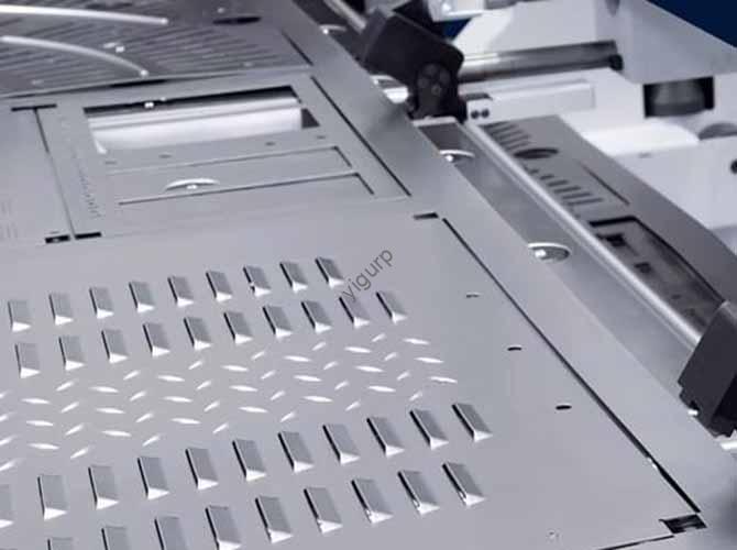
Шаг 1: Резка – The First Transformation
The first step is to cut the 2D flat pattern of your part from a stock sheet of metal. The choice of cutting technology depends on the material, толщина, required precision, и бюджет.
| Техника | Как это работает | Лучше всего для… | Плюс | Минусы |
| Лазерная резка | A high-powered, focused laser beam melts and vaporizes the material, with a gas jet clearing the molten metal. | Точные детали, сложные формы, thin to medium thickness metals (< 0.5 в / 12мм). | Высокая точность (обычно +/- 0.005″), Чистые края, very fast for single parts and low volumes. | Higher initial machine cost, can be challenging on very thick or highly reflective materials like copper. |
| Уотержатная резка | A supersonic stream of water, mixed with a garnet abrasive, erodes the material. | Thick materials (> 1 в / 25мм), heat-sensitive alloys, and virtually any material (металл, пластик, камень, стекло). | No heat-affected zone (Азартный), excellent edge finish, extreme material versatility. | Slower cutting speed than laser, higher operational cost due to consumables (abrasive, сопла). |
| Плазменная резка | An electrically-charged jet of ionized gas (plasma) melts the material, and a high-velocity gas stream blows it away. | Толстый, electrically conductive metals where high precision is not the top priority. | Very fast cutting speeds, бюджетный, excellent for thick steel plates (> 0.5 в / 12мм). | Wider cut path (kerf), less precise than laser/waterjet, creates a significant HAZ that may require secondary cleanup. |
Шаг 2: Изгиб/формирование – Giving It Shape
After the flat pattern is cut, it moves to the нажмите тормоз to be bent into its 3D shape. A press brake is a machine that holds a long, прямой punch (the upper tool) and a V-shaped умирать (the lower tool). The cut metal sheet is placed between them. The punch descends with huge force, pressing the sheet into the die to create a precise bend along a линия изгиба.
This is where DFM rules are critical. The bend radius is determined by the punch’s tip and the die’s opening. The material’s properties, толщина, and the tooling used all influence the final angle, a phenomenon we account for using a k-factor in our calculations to predict and compensate for material springback. Designs with accessible bend lines and standard radii allow for a smooth and efficient forming process.
Шаг 3: Сборка & Hardware Insertion
For multi-part assemblies or parts requiring threaded features, two final fabrication steps are common: welding and hardware insertion.
- Сварка (Тиг/Я): To create strong, permanent joints between two or more sheet metal components, we use welding. Тиг (Вольфрамовый инертный газ) welding is preferred for prototypes as it offers high precision and a clean appearance, ideal for visible joints on aluminum and stainless steel. МНЕ (Металлический инертный газ) is faster and well-suited for steel structures. A good design will provide clear access for the welding torch to reach the joint.
- Hardware Insertion: Tapping threads directly into thin sheet metal is unreliable as it provides very little thread engagement. The professional solution is to use self-clinching fasteners. We use a hardware press to install components like PEM® hardware—studs, standoffs, and nuts—into pre-cut holes. The press embeds the fastener permanently into the sheet, Создание сильного, durable threads that can withstand repeated use.
—
Navigating Common Challenges and How to Overcome Them
Even with perfect DFM, the physical nature of metal fabrication presents challenges. True expertise lies not in avoiding problems, but in anticipating and solving them. Here are common issues we encounter and how we proactively manage them to ensure your part is delivered to spec.
The Problem of Material Warping and Distortion
- The Challenge: “We often see designs with large cutouts or long weld seams on thin material, especially aluminum or stainless steel. The heat from laser cutting or welding introduces stress into the material. Как охлаждается, this stress relieves itself by pulling and twisting the part, causing it to warp and fail to sit flat.”
- Наше решение: “We reduce this in both design and process. In the DFM stage, we recommend adding small stiffening ribs or short perpendicular bends to the design, which greatly increase rigidity with minimal impact on weight or cost. During fabrication, we use a specific sequence of tack welds and controlled heat application to balance stresses across the part. For highly sensitive designs, choosing a cold-cutting process like waterjet, which adds no heat, is a key strategy we use.”
Achieving and Verifying Tight Tolerances
- The Challenge: “A customer specified a very tight positional tolerance of +/- 0.001″ on a feature’s location relative to a bent flange. Given the natural material springback and process variation in bending, this is nearly impossible to achieve with forming alone. Attempting to do so would lead to a high scrap rate and very high cost.”
- Наше решение: “Our first step is always to ask about the *function* of the feature. We worked with the customer to understand *why* that tolerance was so critical. It turned out the precision was only needed for a single bearing bore. We proposed a hybrid manufacturing approach: we fabricated the part with standard bending tolerances (+/- 0.010″), then used a secondary computer-controlled milling operation to precisely machine the critical bore in its final position. This met the functional need perfectly without the cost and uncertainty of trying to over-constrain the entire bending process.”
Miscommunication: Ensuring Your Design Intent is Understood
The most common source of error is not in manufacturing, but in communication. A 3D computer model is a great start, but it doesn’t tell the whole story. To ensure we build exactly what you envision, clear and comprehensive documentation is essential.
- Provide a 2D PDF Drawing: A fully dimensioned 2D drawing is non-negotiable. It should accompany your 3D model and call out all critical dimensions, допуски, material specifications, and finish requirements.
- Point Out Critical-to-Function Features: Use notes on the drawing to tell us *why* a feature is important. A note like “CRITICAL: THIS SURFACE MUST BE FLAT WITHIN 0.1MM” gives us far more context than a simple tolerance callout.
- Specify Hardware: If your design requires self-clinching fasteners, list the exact manufacturer part numbers (НАПРИМЕР., “PEM Part # CLS-M3-1”). This eliminates any confusion about the size, материал, and type of hardware to be installed.
- Define Finish Requirements: Don’t leave finishing to chance. Clearly state the desired outcome, такой как “Sandblast and clear anodize,” “Powder coat, Черный, semi-gloss,” or simply “As-machined with deburred edges.”
—
How to Choose the Right Prototype Sheet Metal Fabricator
Selecting a manufacturing partner is a critical decision. The right partner acts as an extension of your engineering team, adding value far beyond simply cutting and bending metal. The wrong partner can lead to delays, poor quality, и дорогостоящая переделка.
Beyond Price: Key Attributes of a Great Prototyping Partner
While cost is always a factor, it shouldn’t be the only one. Для прототипов, where learning and improvement are key, the value of expertise and support often outweighs a small difference in price.
- Engineering Support: Does the shop offer DFM feedback, or do they just blindly fabricate what you send? A great partner will review your design and actively suggest improvements that save money and improve functionality.
- Clear Communication: Are they responsive, professional, and proactive in asking clarifying questions? Good communication is the foundation of a successful project. Look for a partner who is easy to work with and transparent about their process.
- In-House Capabilities: Does the fabricator have laser cutting, press brakes, hardware insertion, and welding all under one roof? A one-stop shop greatly reduces lead time, simplifies logistics, and ensures one point of accountability for quality.
- Proven Experience: Ask to see examples of similar parts they have made. A portfolio of complex, high-quality work in materials relevant to your project is a strong indicator of capability and experience.
The ‘Right-Fit’ Fabricator Scorecard: A Self-Assessment Tool
To make an objective decision, use this scorecard to evaluate potential vendors based on what matters most for your specific project. Rate your project’s need for each criterion, then score each vendor on a scale of 1-5.
| Evaluation Criterion | My Project’s Need (Low/Med/High) | Vendor A Score (1-5) | Vendor B Score (1-5) | Примечания |
| DFM Feedback & Engineering Expertise | Высокий (My design is complex) | Did they offer suggestions on my RFQ? | ||
| Время выполнения | Высокий (Need it for a trade show) | What is their quoted lead time? | ||
| Material Specialization | Середина (Using standard stainless steel) | Do they stock this material? | ||
| Возможность толерантности | Высокий (Have critical-to-function dimensions) | Can they show proof of similar precision work? | ||
| In-House Finishing (Powder Coat/Anodize) | Низкий (Raw finish is okay for this prototype) | Do they manage this or outsource? | ||
| Контроль качества & Inspection Reports | Середина (Need to verify key dimensions) | Do they offer CMM or FAI reports? |
—
The Final Steps: Post-Fabrication and Finishing
Once a part is cut, наклонный, and assembled, it’s not yet complete. The final steps of finishing and inspection transform it from a raw fabrication into a professional, functional component ready for testing and presentation.
Surface Finishes for Function and Appearance
Finishing processes are applied to protect the part, improve its function, or enhance its appearance. The choice depends entirely on the application.
- As-Machined/Raw: This is the default finish directly from the fabrication process. It’s the most cost-effective option but may have minor scratches or tool marks.
- Deburring/Tumbling: All parts should be deburred to remove sharp edges for safety. Tumbling in abrasive media provides a uniform, гладкий, satin finish and is excellent for preparing parts for plating or anodizing.
- Порошковое покрытие: A durable and cosmetic polymer finish is applied as a dry powder and then cured with heat. It offers excellent protection and is available in a vast range of colors and textures.
- Анодирование (для алюминия): An electrochemical process that creates a hard, коррозионная устойчивость, and non-conductive ceramic layer on the surface of aluminum. It can be dyed in various colors.
- Покрытие (НАПРИМЕР., Цинк, Никель): A thin layer of another metal is deposited onto the part’s surface to add corrosion resistance, improve conductivity, or provide a specific cosmetic look.
Quality Inspection and Verification
The final step before shipping is quality control. Every part we produce is inspected to ensure it meets the specifications laid out in your drawing. For standard dimensions, we use precision tools like digital calipers and height gauges. For parts with complex shapes and tight tolerances, we use a Coordinate Measuring Machine (ШМ), which uses a probe to take highly accurate 3D measurements and compares them directly to your computer model. This final verification ensures that what you receive is exactly what you designed.
—
Заключение: Your Path from Design to a Successful Prototype
The journey from a digital file to a successful physical prototype is a process of thoughtful engineering and skilled execution. It begins not on the shop floor, but at your desk, with a commitment to smart Design for Manufacturability. By creating a design that is naturally efficient to produce, you pave the way for a smooth fabrication process.
This process, executed with the right cutting, изгиб, and assembly techniques, brings your vision to life. The final piece of the puzzle is a strong, communicative partnership with your fabricator—a team that provides not just manufacturing services, but also expertise and guidance. Thoughtful planning and collaboration are the keys to a fast, рентабельный, and ultimately functional outcome. With this knowledge, you are well-equipped to begin your next project with confidence.