Ever picked up amachining drawing and felt overwhelmed by symbols, linhas, e jargão? Você não está sozinho. Quer você seja um novo designer, um técnico de chão de fábrica, ou um inspetor de qualidade, dominar desenhos de usinagem é a chave para transformar ideias em peças precisas. This guide breaks down everything from basic views to advanced tolerancing—with real-world examples to avoid costly mistakes.
1. What Is a Machining Drawing, e por que isso importa?
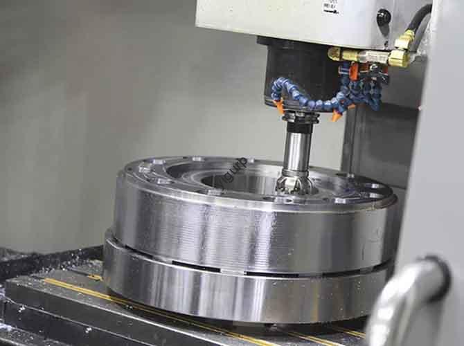
UMmachining drawing (or engineering blueprint) is a visual language that communicates design intent, dimensions, and manufacturing requirements between engineers and production teams. Think of it as a “recipe” for making parts: miss a detail, and the final product might not fit or function.
In my 12 years of working with automotive components, I’ve seen this firsthand. A supplier once misread a thread callout on a brake caliper drawing—resulting in 500 non-functional parts and a $40,000 rework cost. That’s why every line, symbol, and note on a machining drawing carries weight.
2. Mastering Standard Views and Layout
Before diving into details, you need to understand how parts are presented. Olayout of a machining drawing follows strict rules to ensure clarity.
Key Views Explained
| View Type | Purpose | Example Use Case |
|---|---|---|
| Orthographic Projection | 2D views (front, top, side) showing length, width, height | Simple parts like washers or brackets |
| Isometric View | 3D-like view for visualizing shape without distortion | Assemblies or complex housings |
| Section View | Reveals internal features (por exemplo, buracos, cavities) by “corte” the part | Engine blocks with hidden oil passages |
| Detail View | Magnifies small features (por exemplo, tópicos) that are hard to see | Precision gears with fine teeth |
| Auxiliary View | Shows sloped surfaces that don’t align with standard views | Wedge-shaped machine parts |
Must-Have Layout Elements
Every professional drawing includes these sections:
- Title Block: Contains part name, part number, material, and designer info.
- Drawing Border: Defines the document’s edges (per standards like ASME Y14.5).
- Revision Block: Tracks changes (por exemplo, “Rev A: Increased hole diameter to 10mm”).
- Scale: Indicates if the drawing is full-size (1:1) or scaled (por exemplo, 1:2 for large parts).
- Sheet Size: Common sizes include A4 (210×297mm) and ANSI A (8.5×11 inches).
3. Dimensions and Tolerances: The Precision Backbone
Dimensions tell “how big” a part should be—tolerances tell “how much it can vary.” Getting this wrong leads to scrap or assembly failures.
Basic Dimension Types
- Linear Dimension: Measures length, width, or height (por exemplo, “50milímetros”).
- Angular Dimension: Specifies angles (por exemplo, “90° ±0.5°”).
- Diameter Symbol (⌀): Marks circular features (por exemplo, “⌀15mm”).
- Radius Symbol (R): Labels curved edges (por exemplo, “R5mm”).
Tolerancing Methods: Plus/Minus vs. GD&T
Most beginners start withPlus/Minus Tolerancing (por exemplo, “25mm ±0.1mm”), which is simple but limited. For complex parts, Geometric Dimensioning and Tolerancing (GD&T) is essential—it controls shape, location, and orientation more precisely.
Here’s a real example from an aerospace project I worked on: We needed a shaft to fit into a bearing housing. Using plus/minus tolerancing led to 15% of parts jamming because it didn’t account for straightness. Switching to GD&T with aFeature Control Frame (controlling position and straightness relative to aDatum) reduced defects to 0.5%.
Critical GD&T Concepts
- Datum: A reference point/axis (por exemplo, Datum A = part’s bottom surface).
- Basic Dimension: Theoretical exact size (boxed, por exemplo, “50”)—tolerances come from GD&T symbols.
- Tolerance Stack-up: Calculating how individual tolerances add up (critical for assemblies). Tools like 3D CSWA can automate this, but manual checks catch errors early.
4. Geometric Characteristics and Symbols
GD&T uses 14 symbols to control geometric features. Below are the most common ones you’ll see:
| Characteristic | Symbol | What It Controls | Industry Example |
|---|---|---|---|
| Flatness | ⊥ | How flat a surface is | Engine cylinder heads (seal against gaskets) |
| Straightness | / | How straight a line/axis is | Drill bits (prevents wobbling) |
| Position | ⌖ | Location of features (por exemplo, buracos) | Circuit board mounting holes |
| Runout | ⊕ | Vibration when rotating (por exemplo, eixos) | Car wheel hubs (smooth driving) |
| Surface Finish Symbol | ▭ | Roughness of a surface (por exemplo, “Ra 1.6μm”) | Pistons (reduces friction) |
Pro tip: Always pairSurface Finish Symbols with functional requirements. A gear tooth might need Ra 0.8μm for quiet operation, while a non-contact surface could use Ra 6.3μm to cut costs.
5. Annotations and Callouts: Avoid Misinterpretation
Annotations add critical manufacturing details that dimensions alone can’t convey. Here are the ones you’ll use daily:
- Leader Line: Connects notes to features (por exemplo, “Tratamento térmico: HRC 30-35”).
- Hole Callout: Combines size, depth, and type (por exemplo, “⌀8mm THRU, Counterbore ⌀12mm × 3mm”).
- Thread Callout: Specifies thread type (por exemplo, “M10 × 1.5 ISO Metric Coarse”).
- Common Features:
- Chamfer: Beveled edge (por exemplo, “2×45°”)—prevents sharp edges.
- Fillet: Rounded edge (por exemplo, “R3”)—reduces stress concentrations.
- Undercut: Groove for assembly (por exemplo, “0.5mm × 1mm”)—common in bolts.
I once had a supplier misread aCounterbore callout as aCountersink on a flange—they used the wrong tool, e 200 parts had to be re-machined. Adding a simple note (“Use 12mm counterbore tool”) fixed the issue.
6. Drawing Standards and File Types
Machining drawings follow global standards to ensure consistency across borders. The two main systems are:
ASME vs. ISO: Principais diferenças
| Aspect | ASME Y14.5 (North America) | ISO GPS (Europe/Global) |
|---|---|---|
| Default Rule | Principle of Inclusiveness (MMC applies by default) | independent principle (Tolerances apply independently) |
| Contour Tolerance | Allows composite profile tolerances | No composite profile tolerances |
| Projection | Third-Angle Projection (views: front→top→right) | First-Angle Projection (views: front→bottom→left) |
Source: ASME Y14.5-2009 and ISO 1101:2012 padrões .
Common File Types
| File Type | Use Case |
|---|---|
| DWG | Editable CAD files (AutoCAD, SolidWorks) |
| DXF | Interchangeable format (works across different CAD software) |
| Non-editable for sharing with suppliers/inspectors | |
| MBD | 3D model with embedded dimensions (replacing 2D blueprints—see below) |
7. The Future: Model-Based Definition (MBD)
For decades, 2D Blueprints were the norm—butModel-Based Definition (MBD) is changing the game. MBD embeds all dimensions, tolerances, and notes directly into a 3D CAD model, eliminating the need for separate drawings.
In a recent electric vehicle project, we switched from 2D to MBD for battery housing parts. Here’s what happened:
- Inspection time dropped by 40% (we used CT scans for Digital FAI instead of calipers) .
- Supplier errors fell by 25% (3D models are harder to misinterpret than 2D views).
- Design iterations speeded up—changes to the 3D model updated automatically, no more re-drawing blueprints.
The catch? MBD requires cross-team training (designers, maquinistas, inspectors) and compatible CAD tools. But for high-volume or complex parts, the ROI is undeniable.
Yigu Technology’s Perspective
Machining drawings are the bridge between design and manufacturing, but their form is evolving. Na tecnologia Yigu, we’ve observed that 60% of manufacturing errors stem from ambiguous 2D drawings—hence our focus on MBD integration. MBD isn’t just a “trend”; it’s a necessity for precision-critical industries like aerospace and EVs. We advise clients to start small: pilot MBD for one part family, train teams on GD&T fundamentals, and use digital inspection tools to validate results. The goal isn’t to abandon tradition, but to merge it with technology for faster, more accurate production.
Perguntas frequentes
Q1: What’s the difference between a detail view and an auxiliary view?
UMdetail view magnifies a small part of the drawing (por exemplo, a thread). Anauxiliary view shows a sloped surface that can’t be fully seen in standard views (por exemplo, a ramp on a bracket).
Q2: When should I use GD&T instead of plus/minus tolerancing?
Use GD&T for:
- Complex parts with multiple features (por exemplo, engine blocks).
- Assemblies where position/orientation matter (por exemplo, gearboxes).
- Reducing manufacturing costs (GD&T allows looser tolerances where they don’t affect function).
Q3: Is MBD replacing 2D blueprints entirely?
Not yet. Small shops or simple parts (por exemplo, washers) still use 2D drawings because they’re cheaper and simpler. But MBD is becoming standard for automotive, aeroespacial, e dispositivos médicos.
Q4: How do I avoid tolerance stack-up issues?
- Use GD&T with datums to control critical features.
- Calculate stack-up early (use tools like VisVSA or Excel spreadsheets).
- Test with prototypes—measure actual part variation before mass production.