Chaves elétricas de descongelamento por calor são ferramentas essenciais para descongelar parafusos/porcas congelados em manutenção industrial e automotiva. Seus protótipos, relying on Usinagem CNC to integrate structural precision and heating functionality, determinar diretamente se o produto final atende aos padrões de eficiência e segurança. This article systematically breaks down the full CNC machining process for electric heat thawing wrench prototypes, addressing core challenges like thermal insulation, heating uniformity, and structural durability.
1. Pre-Machining: Projeto & Seleção de Materiais
A scientific design and appropriate material pairing lay the groundwork for a functional prototype. This stage focuses on balancing heating efficiency, resistência estrutural, and machining feasibility.
1.1 Demand Analysis & 3Modelagem D
Clarifying functional and structural requirements first avoids costly rework during machining.
Demand Analysis Breakdown
| Requirement Type | Key Details | Impact on CNC Machining |
| Heating Function | Confirm target temperature range (40-80°C), heating speed (≤5 mins to reach 60°C), and heating method (electric heating film/PTC heating sheet) | Determines the size and position of the heating element cavity (tolerância ±0,05 mm) in the wrench head |
| Structural Design | Define wrench head size (por exemplo, 50mm×30mm for M16 bolts), handle length (150-200mm for ergonomics), and grip texture | Influences toolpath planning (por exemplo, avoiding undercuts in the heating cavity; machining anti-slip textures with 0.2mm depth) |
| Padrões de segurança | Ensure handle surface temperature ≤45°C (anti-scalding); waterproof level ≥IPX4 (for wet environments) | Requires precise machining of thermal insulation gaps (1-2mm between heating layer and handle) and sealed circuit cavities |
3Modelagem D & Engineering Drawing Tips
- Software Choice: Usar SolidWorks ou UG NX to create modular models—split the wrench into 3 core parts: wrench head (heating zone), lidar (insulation zone), e circuit cavity (temperature control zone) for step-by-step machining.
- Critical Design Notes:
- Reserve 0.5mm extra space in the heating element cavity to accommodate thermal expansion of the electric heating film.
- Projeto honeycomb heat dissipation holes (diameter 3mm, spacing 8mm) in the handle to prevent overheating—ensure hole positioning accuracy (±0,1 mm) for uniform airflow.
1.2 Material Comparison for Core Components
Material selection directly affects heating efficiency, durabilidade, and machining difficulty.
| Componente | Optional Materials | Vantagens | Desvantagens | Machining Recommendations |
| Wrench Head (Heating Zone) | Liga de alumínio (6061) | Excelente condutividade térmica (167 S/m·K), leve | Low corrosion resistance | Use ferramentas de metal duro; coolant required to reduce burrs |
| Aço inoxidável (304) | Alta resistência à corrosão, alta resistência | Má condutividade térmica (16 S/m·K) | Slow feed speed (80-120 mm/min) para evitar o desgaste da ferramenta | |
| Handle (Insulation Zone) | Plástico de Engenharia (PC) | Good insulation, resistência ao calor (até 120ºC) | Low impact resistance | Ferramentas de aço rápido; compressed air cooling to prevent melting |
| Nylon 66 | Alta tenacidade, anti-slip | Low heat resistance (≤80°C) | Finish with 800# sandpaper to smooth surface | |
| Thermal Insulation Layer | Silicone Pad (FDA-Certified) | Resistência a altas temperaturas (até 200ºC), boa flexibilidade | Low structural strength | Cut to size post-CNC; no machining required |
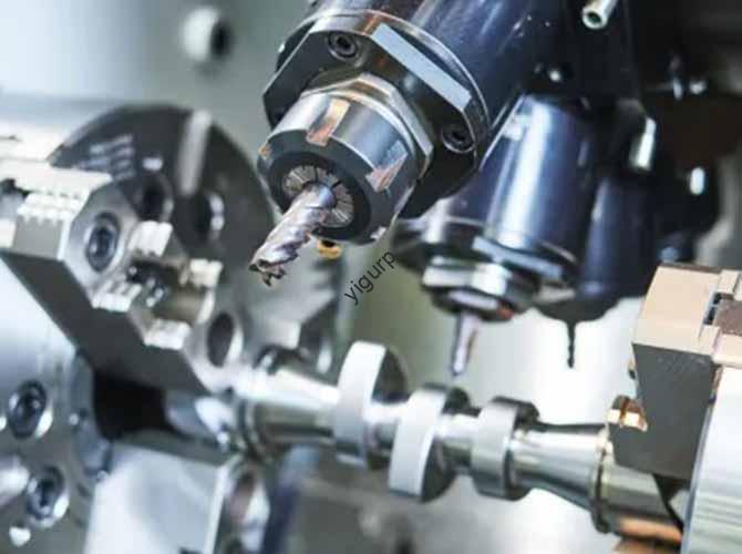
2. CNC Machining Stage: Configurar & Execution
This stage transforms raw materials into precision components, requiring strict control over machine selection, toolpaths, e precisão.
2.1 Machine Tool & Seleção de ferramentas
Matching machines and tools to component materials ensures efficiency and accuracy.
| Componente | Recommended Machine Type | Suitable Tools | Tool Size (milímetros) | Machining Purpose |
| Aluminum Alloy Wrench Head | Centro de Usinagem Vertical (por exemplo, DMG MORI) | Flat Bottom Cutter (Desbaste), Ball Head Cutter (Acabamento) | Φ8-10 (Desbaste), Φ3-5 (Acabamento) | Machine heating cavity; chamfer edges (0.5milímetros) |
| Stainless Steel Wrench Head | High-Torque Machining Center | Tungsten Carbide End Mill | Φ6-8 | Cut heat dissipation grooves; ensure cavity flatness (≤0,1 mm) |
| PC Handle | 3-Axis CNC Engraving Machine (por exemplo, 3018 Pro) | Spiral End Mill | Φ4-6 | Machine grip texture; drill circuit cavity holes |
2.2 Programação & Parâmetros de Usinagem
Optimized G-code and parameters prevent material damage and ensure precision.
Key Machining Parameters by Material
| Material | Rotational Speed (RPM) | Velocidade de alimentação (mm/min) | Profundidade de corte (milímetros) | Special Requirements |
| Liga de alumínio (6061) | 8,000 – 12,000 | 150 – 250 | 1.0 – 1.5 | Use emulsion coolant; avoid high speed to prevent chip buildup |
| Aço inoxidável (304) | 5,000 – 8,000 | 80 – 120 | 0.5 – 1.0 | Apply cutting oil; reduce depth of cut to avoid tool breakage |
| PC Plastic | 10,000 – 15,000 | 200 – 300 | 0.8 – 1.2 | Compressed air cooling; sem refrigerante (prevents material warping) |
Toolpath Optimization Tips
- Usinagem Desbaste: For the wrench head’s heating cavity, use a zigzag toolpath to remove 90% of excess material—reduce machining time by 30% compared to linear paths.
- Acabamento: For the handle’s grip texture, use a spiral toolpath to ensure uniform groove depth (0.2mm ±0.02mm)—avoiding uneven pressure during use.
- Circuit Cavity: Use um peck drilling cycle to machine holes (diâmetro 5mm) for wire routing—prevents chip clogging and ensures hole straightness.
2.3 Machining Precautions
- Fixing & Posicionamento:
- Secure metal blanks with a vise + precision locating pins (tolerance ±0.01mm) to avoid vibration during machining.
- Fix plastic sheets with double-sided adhesive tape (high-temperature resistant) to prevent surface scratches.
- Controle de precisão:
- Maintain flatness tolerance ≤0.1mm for the wrench head’s heating cavity—ensures tight fit with the electric heating film.
- Controlar hole position tolerance ±0.1mm for the circuit cavity—avoids wire pinching during assembly.
3. Heating System Integration & Conjunto
Integrating heating elements and electronics turns components into a functional prototype.
3.1 Heating Element Installation
Proper installation ensures uniform heating and safety.
Two Common Heating Solutions (Comparação)
| Solução | Installation Steps | Vantagens | Desvantagens |
| Electric Heating Film | 1. Clean the wrench head cavity with alcohol.2. Apply thermal conductive silicone grease (thickness 0.1mm) to the cavity.3. Paste the heating film (power density 1.5 W/cm²) and press for 5 minutos. | Fast installation, uniform heating | Low mechanical strength; easy to tear |
| PTC Heating Sheet | 1. Machine 4 fixing holes (diameter 2mm) around the cavity.2. Apply thermal grease to the PTC sheet.3. Secure the sheet with M2 screws (torque 0.2 N·m). | Alta durabilidade, stable temperature | Heating uniformity depends on grease application |
3.2 Temperature Control System Integration
This system ensures safe and precise temperature regulation.
Component Selection & Wiring
| Componente | Model/Specification | Installation Notes |
| Temperature Sensor | NTC 10KΩ (±1%) | Embed in the wrench head (1mm from heating element); seal with high-temperature glue |
| Controller | PID Module (SSR Solid-State Relay) | Install in the handle’s circuit cavity; isolate from heating zone with silicone pad |
| Mostrar | OLED Screen (128×64 pixels) | Mount on the handle; ensure 0.5mm gap for heat dissipation |
| Wiring | High-Temperature Silicone Wire (18AWG) | Route through pre-machined holes; wrap with fiberglass tape for insulation |
3.3 Step-by-Step Assembly (Linear Narrative)
- Thermal Insulation Layer Installation: Paste the silicone pad (thickness 1mm) between the wrench head and handle—ensure no gaps to prevent heat transfer to the handle.
- Heating Element Connection: Solder the heating film/PTC sheet to the controller; test resistance (alvo: 50-100Ω) to confirm no short circuits.
- Handle Assembly: Secure the handle to the wrench head with M3 screws (torque 0.3 N·m); add a waterproof rubber ring (diameter 8mm) at the joint to meet IPX4 standards.
- Final Checks: Verify all wires are neatly routed; ensure the display is aligned with the handle’s window (no offset >0.5mm).
4. Teste & Otimização
Rigorous testing identifies issues, while optimization improves performance.
4.1 Key Test Items & Padrões
| Test Category | Test Method | Pass Standard |
| Heating Performance | Set temperature to 60°C; use an infrared thermometer to measure 5 points on the wrench head | Temperature difference ≤±3°C; reach target in ≤5 mins |
| Controle de temperatura | Set temperature to 70°C; monitor for 1 hour with a data logger | Fluctuation ≤±1°C; auto-shutdown when exceeding 80°C |
| Segurança | 1. Measure handle temperature after 1 hour of operation.2. Conduct IPX4 water splashing test | Handle temperature ≤45°C; no short circuits after splashing |
| Durabilidade | Simulate 500 usa (cada: heat to 60°C, cool to room temperature) | No loose parts; heating performance unchanged |
4.2 Optimization Directions
- Heating Uniformity: If temperature differences exceed 3°C, reapply thermal conductive grease (ensure even coverage) or adjust the heating film’s position.
- Handle Comfort: If grip texture is too rough, refinish with 1000# lixa; if too smooth, re-machine grooves (depth increased to 0.3mm).
- Redução de peso: Machine 4 lightening holes (diameter 6mm) in the handle’s non-load-bearing area—reduce weight by 15% without affecting strength.
Yigu Technology’s Viewpoint
For CNC machining of electric heat thawing wrench prototypes, thermal balance and safety are core. Yigu Technology suggests prioritizing material matching: liga de alumínio 6061 for the wrench head ensures efficient heat transfer, while PC plastic for the handle guarantees anti-scalding. In machining, focus on the heating cavity’s flatness (≤0,1 mm)—even a tiny gap will reduce heating efficiency. Post-assembly, strict IPX4 testing is non-negotiable for wet workplaces. Olhando para frente, integrating IoT sensors (por exemplo, wireless temperature monitoring) will be a trend, requiring CNC machining to reserve space for tiny electronic modules—demanding tighter tolerances (±0,03mm) and micro-tool applications.
Perguntas frequentes
- What CNC machine is best for machining the aluminum alloy wrench head’s heating cavity?
A vertical machining center (por exemplo, DMG MORI) é ideal. It offers high rigidity and precision (±0,005 mm), ensuring the heating cavity’s flatness and size meet requirements—critical for tight fit with the heating element.
- How to prevent the PC handle from warping during CNC machining?
Use high rotational speeds (10,000-15,000 RPM) and moderate feed speeds (200-300 mm/min). Adicionalmente, use compressed air to cool the material continuously—avoids localized heat buildup that causes warping.
- Why is thermal conductive silicone grease necessary between the heating element and wrench head?
It fills tiny gaps (≤0,1 mm) between the two surfaces, reducing thermal resistance. Sem isso, air gaps would significantly lower heat transfer efficiency—leading to uneven heating and longer thawing times.