CNC five-axis linkage machining prototype is a game-changing technology in modern manufacturing, permitindo a criação de alta precisão, protótipos complexos que a usinagem tradicional de 3 eixos simplesmente não consegue igualar. Combinando três eixos lineares (X, S, Z) com dois eixos rotativos, este método oferece flexibilidade incomparável – perfeito para peças com superfícies curvas complexas, furos angulares, ou recursos multifacetados, such as aerospace components, peças de motor automotivo, ou caixas de dispositivos médicos. For product engineers testing new designs or procurement specialists sourcing reliable prototypes, understanding the ins and outs of CNC five-axis linkage machining prototype is key to avoiding delays, reduzindo o desperdício, and ensuring final parts meet strict performance standards. Este guia detalha todo o processo, with real-world examples and data to make every step actionable.
1. Projeto & Programação: The Foundation of Five-Axis Prototyping
O sucesso de CNC five-axis linkage machining prototype starts with precise design and programming. Skipping these steps or cutting corners leads to misaligned features, rough surfaces, or even machine damage.
1.1 3D CAD Design: Model Every Detail
Primeiro, usar CAD (Design Assistido por Computador) programas (por exemplo, SolidWorks, AutoCAD, or Fusion 360) to create a detailed 3D model of the prototype. For five-axis machining, this means defining every complex feature:
- Curved surfaces: Specify radii, tangency, and arc lengths (critical for parts like turbine blades or automotive wheel arches).
- Angled holes: Mark hole positions and angles relative to other features (por exemplo, a 45° hole in a bracket that must align with a mating part).
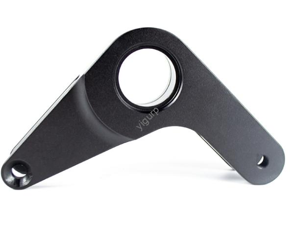
- Multi-sided features: Ensure all sides of the prototype are modeled, as five-axis machines can access hard-to-reach areas without repositioning.
Why Precision Matters: A medical device manufacturer once missed a 0.2mm error in the CAD model of a surgical tool prototype. When machined, the curved handle didn’t fit the grip design—delaying testing by 3 weeks and costing $1,500 in rework.
1.2 Programação CAM: Convert Design to Machine Code
Próximo, CAM (Fabricação Assistida por Computador) programas translates the CAD model into G-code (a linguagem que as máquinas CNC entendem). For five-axis prototypes, CAM does three critical things:
- Tool path planning: Maps the tool’s movement across all five axes to avoid collisions (por exemplo, preventing the tool from hitting the machine’s spindle or fixture).
- Tool selection: Recommends tools based on material and feature size (por exemplo, a ball-nose end mill for curved surfaces, a drill for angled holes).
- Cutting parameter setting: Defines speed, taxa de alimentação, and depth of cut to balance efficiency and quality.
Pro Tip: Use CAM’s simulation feature to test the tool path virtually. An aerospace supplier used this to fix a collision risk in a turbine prototype program—saving $5,000 in potential machine damage.
2. Seleção de Materiais: Match to Prototype Needs
Choosing the right material for CNC five-axis linkage machining prototype directly impacts machinability, prototype performance, e custo. Below’s a breakdown of top options, suas propriedades, e usos ideais:
| Tipo de material | Propriedades principais | Ideal Prototype Uses | Usinabilidade (1–10) | Custo (USD/kg) |
| Plástico ABS | Baixo custo, easy to shape | Consumer product casings | 9 | \(2.5 – \)4.0 |
| PC (Policarbonato) | Alta resistência ao impacto, transparente | Invólucros para dispositivos médicos, capas de farol | 7 | \(3.8 – \)6.0 |
| Liga de alumínio 6061 | Leve, resistente à corrosão | Automotive chassis parts, suportes aeroespaciais | 8 | \(2.8 – \)4.5 |
| Aço inoxidável 304 | Durável, à prova de ferrugem | Componentes de equipamentos industriais | 5 | \(3.8 – \)6.5 |
| Titanium Alloy Ti-6Al-4V | Ultra-forte, resistente ao calor | Peças de motor aeroespacial | 3 | \(35 – \)50 |
Real-World Example: An automotive startup needed a prototype for a lightweight engine bracket. They chose liga de alumínio 6061 for its high machinability (score of 8) e propriedades leves. The five-axis machine cut the bracket’s complex curved edges in 2 hours—3x faster than stainless steel—and the prototype met all strength tests.
3. Machine & Configuração da ferramenta: Prepare for Five-Axis Machining
Even the best design and material won’t save CNC five-axis linkage machining prototype if the machine and tools are poorly set up. This phase focuses on ensuring accuracy and safety.
3.1 Choose the Right Five-Axis Machine
Not all five-axis machines are the same—select one based on your prototype’s complexity:
- Trunnion-type machines: Ideal for small to medium prototypes (por exemplo, medical tool handles). They rotate the workpiece on two axes, keeping the tool stable.
- Head-type machines: Better for large prototypes (por exemplo, automotive chassis frames). The tool head rotates on two axes, allowing access to large parts.
Data Point: Trunnion-type machines offer ±0.002mm positional accuracy, while head-type machines provide ±0.005mm—both far more precise than 3-axis machines (±0,01 mm).
3.2 Seleção de ferramentas & Calibration
Tools for five-axis machining must be durable and precisely calibrated:
- Tool types: Use carbide tools for metals (they resist wear better than HSS tools) e aço rápido (HSS) ferramentas para plásticos. For curved surfaces, a ball-nose end mill with a 0.5mm radius ensures smooth cuts.
- Calibration: Use a tool setter to measure tool length and diameter with ±0.001mm accuracy. A mis calibrated tool can create 0.1mm errors in prototype dimensions—enough to ruin a part.
Common Mistake: A manufacturer skipped tool calibration for a stainless steel prototype. The tool was 0.05mm shorter than measured, leading to shallow holes that didn’t align with mating parts. Recalibrating and re-machining cost 8 extra hours.
4. Core Machining Process: Roughing, Acabamento & Strategy
The heart of CNC five-axis linkage machining prototype is the actual cutting process, which happens in two main stages: roughing and finishing. A well-planned strategy ensures efficiency and quality.
4.1 Roughing: Remove Excess Material Fast
Roughing’s goal is to quickly strip away most of the machining allowance (usually 3–5mm) while leaving enough material for finishing. Key steps:
- Cutting parameters: Use a high feed rate (200–300 mm/min for aluminum) and deep cuts (2–3mm per pass) to save time.
- Tool path: Use a “zig-zag” path to cover large areas efficiently—avoiding sharp turns that cause vibration.
Exemplo: A furniture designer roughing a curved chair arm prototype (liga de alumínio 6061) used a 2mm depth of cut and 250 mm/min feed rate. The machine removed 90% of excess material in 45 minutos.
4.2 Acabamento: Refine to Precision
Finishing ensures the prototype meets all dimensional and surface quality requirements. Key steps:
- Cutting parameters: Slow the feed rate (100–150 mm/min) and reduce depth of cut (0.1–0.5mm per pass) to avoid tool marks.
- Surface focus: For curved surfaces, use a “spiral” tool path to create a smooth finish (Rá 0.8 μm or better).
Estudo de caso: An aerospace company finishing a turbine blade prototype used a 0.2mm depth of cut and 120 mm/min feed rate. The five-axis machine’s rotary axes allowed the tool to follow the blade’s complex curve seamlessly, resulting in a surface roughness of Ra 0.4 μm—meeting aerospace standards.
5. Controle de qualidade & Pós-processamento
CNC five-axis linkage machining prototype doesn’t end with cutting—quality control and post-processing ensure the prototype is ready for testing.
5.1 Controle de qualidade: Catch Errors Early
Use these tools to verify prototype accuracy:
- Máquina de medição por coordenadas (CMM): Maps all features in 3D to check dimensional accuracy. For a bracket prototype with angled holes, a CMM can confirm hole angles are within ±0.1°.
- Surface Roughness Tester: Measures Ra values to ensure smoothness (por exemplo, Rá 1.6 μm for non-critical parts, Rá 0.8 μm for sealing surfaces).
- Inspeção Visual: Check for scratches, rebarbas, or tool marks—these can affect both appearance and function.
5.2 Pós-processamento: Enhance Performance & Aparência
After passing inspection, finish the prototype with these steps:
- Cleaning: Use a degreaser to remove coolant and metal chips—pay extra attention to holes and crevices.
- Rebarbação: Use a deburring tool to remove sharp edges (critical for parts that people handle, like tool grips).
- Tratamento de superfície: Apply anodizing (para alumínio) to improve corrosion resistance, ou pintura (para produtos de consumo) to match final production parts.
Yigu Technology’s View on CNC Five-Axis Linkage Machining Prototype
Na tecnologia Yigu, nós nos especializamos em CNC five-axis linkage machining prototype para o setor aeroespacial, automotivo, and medical clients. Sobre 12 anos, we’ve refined our process to prioritize precision: we use high-end trunnion-type machines for small prototypes (±0.002mm accuracy) and head-type machines for large parts, select materials based on client needs (por exemplo, alumínio para peças leves, titanium for high-strength components), and employ CMM inspections for 100% of prototypes. Our team also offers design support—helping clients optimize CAD models for five-axis machining to cut time by 25%. For us, great five-axis prototypes aren’t just about meeting specs—they’re about helping clients turn innovative ideas into real-world products faster.
FAQ About CNC Five-Axis Linkage Machining Prototype
Q1: How long does CNC five-axis linkage machining prototype take?
UM: It depends on size and complexity. A small medical tool prototype (50x30x20mm) takes 2–3 hours. A large automotive chassis part (500x300x200mm) with complex curves takes 8–10 hours. Batch size also matters—10 identical prototypes take ~1.5x longer than 1, thanks to repeatable settings.
Q2: Is CNC five-axis linkage machining prototype more expensive than 3-axis?
UM: Sim, but the extra cost is worth it for complex parts. Five-axis machining costs 20–30% more upfront, but it eliminates the need for repositioning (which causes errors) and reduces rework by 50%. For a turbine blade prototype, five-axis machining saves $2,000 in rework compared to 3-axis.
Q3: Can CNC five-axis linkage machining prototype handle plastic materials?
UM: Absolutamente! Plastics like ABS and PC are easy to machine with five-axis technology. They’re cheaper than metals and ideal for early design tests (por exemplo, consumer product casings). We often recommend plastic prototypes for initial user testing, then metal for final performance tests.