Rapid prototype machining is a core part of modern product development, enabling teams to turn design concepts into physical models quickly. Unlike traditional prototyping, it emphasizes speed without compromising on verifying design feasibility. Whether you’re developing a new electronic device or an automotive component, understanding the full process of rapid prototype machining helps you avoid delays, コストを削減します, and ensure the final prototype aligns with your goals. Below is a detailed breakdown of each stage, with practical tips and data to guide your project.
1. Design Phase: Lay the Groundwork for Successful Prototyping
The design phase is where your product idea takes shape digitally—and it directly impacts the efficiency of subsequent machining. Rushing this step often leads to rework later, so investing time here pays off.
Key Tasks in the Design Phase
- Create Detailed CAD Models: Use professional コンピューター支援設計 (CAD) ソフトウェア (such as SolidWorks, AutoCAD, or Fusion 360) to draw 3D models of the product. These models must include every detail: 寸法, part connections, and even surface textures. According to industry data, accurate CAD models reduce post-machining adjustments by up to 40%.
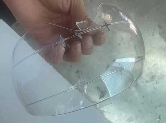
- Select Materials and Processes Early: Based on your product’s end use (例えば。, heat resistance for automotive parts, transparency for display cases), choose suitable materials and machining methods. 例えば:
- If you need a prototype with high impact resistance for a phone case, ABSプラスチック is a good choice.
- If the prototype requires metal-like strength for a mechanical part, 3D printing with metal-infused resin または CNC machining of aluminum works better.
Common Mistakes to Avoid in Design
- Ignoring machining limitations (例えば。, designing overly thin walls that 3D printing can’t support).
- Forgetting to add tolerances (critical for parts that need assembly).
2. 材料の準備: Ensure Compatibility with Machining Methods
The right material preparation ensures smooth machining and a prototype that matches your design intent. Different methods require different material forms—using the wrong form can damage equipment or ruin the prototype.
Material Preparation by Machining Method
| Machining Method | Required Material Form | 一般的な材料 | Preparation Tips |
| CNC加工 | Solid blocks, sheets, or rods | アルミニウム, 真鍮, 腹筋, PMMA | Cut the material to a size slightly larger than the final prototype (add 5-10mm for machining allowance). |
| 3D印刷 | Filaments (for FDM), 樹脂 (for SLA), metal powders (for SLM) | プラ, 腹筋, 樹脂, titanium alloy powder | Dry filaments/resins (moisture causes bubbles in 3D prints); sift metal powders to remove clumps. |
| Silicone Molding | Liquid resins or plastics (for casting) | Polyurethane resin, エポキシ樹脂 | Mix the material strictly according to the manufacturer’s ratio (例えば。, 1:1 for most polyurethane resins) to avoid curing issues. |
Material Quality Check
Before machining, verify:
- Material purity (例えば。, no impurities in metal blocks that could dull CNC tools).
- Material thickness uniformity (critical for consistent 3D print layers).
3. Manufacturing Phase: Choose the Right Method for Speed and Quality
Rapid prototype machining offers three main manufacturing methods, それぞれがユニークな強みを持っています. Your choice depends on factors like prototype complexity, バッチサイズ, and lead time.
Comparison of Rapid Prototyping Manufacturing Methods
| 方法 | スピード (リードタイム) | Cost for 1-10 プロトタイプ | に最適です | 重要な利点 |
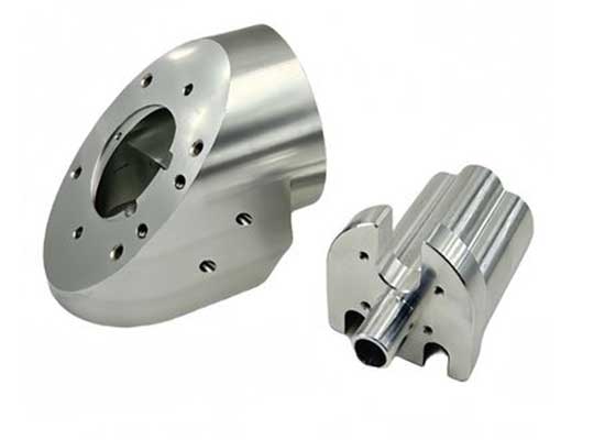
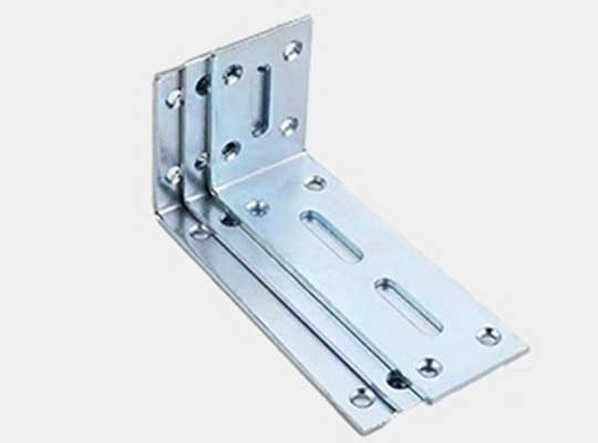
| CNC加工 | 1-3 日 | \(50-\)500 per prototype | 精密部品 (例えば。, ギア, メタルブラケット) | High accuracy (tolerances as tight as ±0.005mm); suitable for hard materials. |
| 3D印刷 | 4-24 時間 | \(20-\)200 per prototype | Complex shapes (例えば。, lattice structures, curved shells) | Fastest for single prototypes; no need for molds. |
| Silicone Molding | 3-7 日 (including mold making) | \(10-\)80 per prototype | Small-batch plastic parts (例えば。, 5-50 identical phone cases) | Low cost for multiples; replicates fine details well. |
実用的な例
必要に応じて 1 prototype of a complex drone frame (with hollow sections) in 24 時間, 3D印刷 (SLA) 理想的です. 必要に応じて 10 identical metal brackets for a machine in 3 日, CNC加工 is more efficient than 3D printing 10 別々の部品.
4. 後処理: Refine the Prototype’s Appearance and Performance
Raw prototypes (right after machining) often have flaws like burrs, rough surfaces, or uneven colors. Post-processing fixes these issues and makes the prototype look and function like the final product.
Step-by-Step Post-Processing Workflow
- Cleaning and Deburring:
- Use brushes, サンドペーパー (80-120 grit for initial cleaning), or chemical deburring agents to remove excess material. For CNC-machined metal parts, a deburring tool can eliminate sharp edges in 5-10 パーツあたりの分.
- Sanding and Polishing:
- Sand the surface with progressively finer sandpaper (から 240 grit to 2000 グリット) 粗さを減らすため. For plastic prototypes, polishing with a buffing wheel and wax can achieve a glossy finish (surface roughness Ra ≤ 0.2μm).
- Surface Treatment:
- スプレー: Apply paint or powder coating for color and corrosion resistance (common for automotive prototypes). Drying time is usually 2-4 hours at room temperature.
- 電気めっき: Add a metal layer (例えば。, クロム, ニッケル) to metal prototypes to improve wear resistance (extends prototype lifespan by 30% in testing).
- Anodizing: For aluminum prototypes, anodizing creates a durable oxide layer (available in colors like black or silver) that resists scratches.
5. Inspection and Testing: Verify Quality and Functionality
A prototype isn’t useful if it doesn’t meet design standards. Inspection ensures dimensional accuracy, while testing confirms it works as intended.
Inspection Methods and Tools
| Inspection Type | 使用されるツール | Acceptance Criteria |
| Dimensional Inspection | Calipers (小さな部分の場合), micrometers, Coordinate Measuring Machines (CMM) | All dimensions must be within ±0.1mm (for general parts) or ±0.01mm (for precision parts like gears). |
| Surface Quality Inspection | Surface roughness tester, visual inspection | No scratches, 泡, or uneven coating; surface roughness Ra ≤ 0.8μm for visible parts. |
Functional Testing Checklist
- Mechanical Testing: For moving parts (例えば。, hinges), test the number of smooth operations (aim for ≥ 1000 cycles without jamming).
- Environmental Testing: If the product will be used outdoors, test the prototype’s resistance to water (IPX4 rating or higher) and temperature (-20°C to 60°C for most consumer products).
- Assembly Testing: If the prototype has multiple parts, check if they fit together without force (gaps should be ≤ 0.2mm).
6. Revision and Optimization: Fix Issues Before Mass Production
Even with careful planning, prototypes may fail tests. The revision phase turns these failures into improvements—saving you from costly mistakes in mass production.
How to Approach Revisions
- Analyze Failure Causes: If a prototype cracks during strength testing, the issue could be:
- The wrong material (例えば。, PLA instead of ABS for a load-bearing part).
- A design flaw (例えば。, a weak joint).
- Update CAD Models and Processes: Modify the CAD file to fix design issues, and adjust machining parameters if needed (例えば。, increasing 3D print layer adhesion for better strength).
- Re-Machine and Retest: Prioritize critical fixes first—for example, if a part doesn’t fit, fix the dimension before re-testing functionality.
Data on Revision Impact
Industry studies show that each round of prototype revision improves design maturity by 25%. Most projects require 1-2 revisions to meet all requirements.
7. Delivery and Customer Feedback: Close the Loop for Improvement
Once the prototype passes all tests, deliver it to the customer and collect feedback. This step ensures the prototype aligns with the customer’s vision and identifies any unstated needs.
Delivery Best Practices
- Include a test report (with dimensional data and functional test results) to demonstrate quality.
- Package the prototype with protective materials (例えば。, foam, bubble wrap) to avoid damage during shipping.
Feedback Collection Tips
- Ask specific questions: “Does the prototype’s weight meet your expectations?” or “Is the button placement easy to use?」
- Record feedback in a shared document (例えば。, Google Docs, Trello) to track changes for future iterations.
Yigu Technology’s View on Rapid Prototype Machining
Yiguテクノロジーで, we believe rapid prototype machining is more than just “making a model”—it’s a bridge between design and market. We prioritize speed without cutting corners: our team uses advanced CAD software to optimize designs for machining, selects materials based on real-world use cases, and tests every prototype with CMMs and functional tools. We also offer flexible options, from 24-hour 3D printing for urgent projects to CNC machining for high-precision parts. By focusing on customer feedback, we help turn prototypes into successful products faster—saving time and resources for our clients.
よくある質問
Q1: How long does a typical rapid prototype machining process take?
A1: It depends on the method and complexity. A simple 3D-printed prototype (例えば。, a small plastic part) can be done in 4-24 時間. A complex CNC-machined metal prototype may take 1-3 日. Silicone molding (including mold making) usually takes 3-7 days for small batches.
Q2: Can I use the same material for the prototype and the final product?
A2: Yes—if the material is compatible with rapid machining methods. 例えば, if your final product uses aluminum, you can CNC machine an aluminum prototype. For materials that are hard to machine (例えば。, 炭素繊維), you can use a similar material (例えば。, carbon fiber-infused plastic) for the prototype to simulate performance.
Q3: What should I do if my prototype fails functional testing?
A3: 初め, work with your machining team to find the root cause (例えば。, 材料, デザイン, or machining error). それから, update the CAD model or adjust the process—for example, if a 3D-printed part is too brittle, switch to a stronger filament (like PETG) or increase layer adhesion. Retest the revised prototype until it meets your requirements.