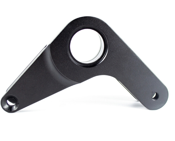
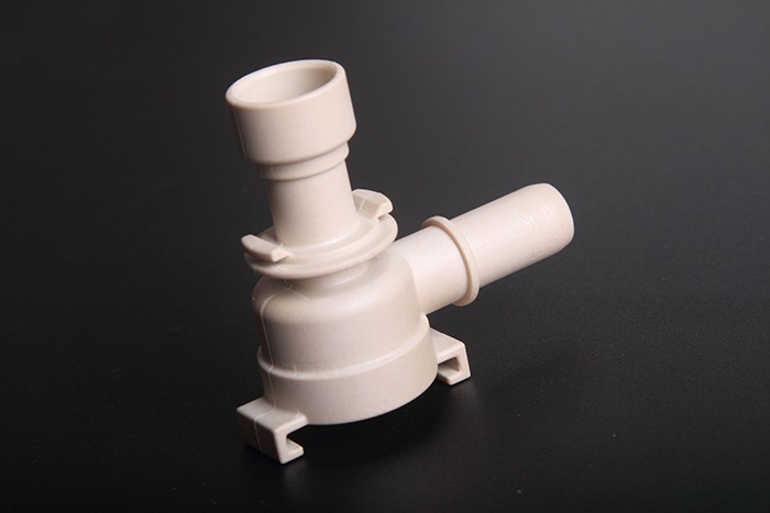
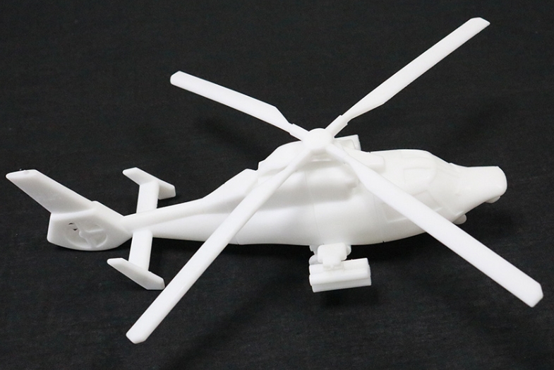
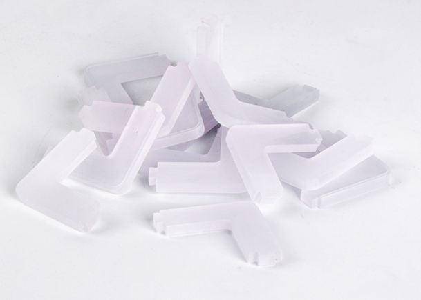
CNC five-axis linkage machining prototype is a game-changing technology in modern manufacturing, enabling the creation of high-precision, complex prototypes that traditional 3-axis machining simply can’t match. By combining three linear axes (x, y, z) with two rotary axes, this method delivers unmatched flexibility—perfect for parts with intricate curved surfaces, angled holes, or multi-sided features, such as aerospace components, automotive engine parts, or medical device housings. For product engineers testing new designs or procurement specialists sourcing reliable prototypes, understanding the ins and outs of CNC five-axis linkage machining prototype is key to avoiding delays, 廃棄物を減らす, and ensuring final parts meet strict performance standards. This guide breaks down the entire process, with real-world examples and data to make every step actionable.
1. デザイン & プログラミング: The Foundation of Five-Axis Prototyping
の成功 CNC five-axis linkage machining prototype starts with precise design and programming. Skipping these steps or cutting corners leads to misaligned features, rough surfaces, or even machine damage.
1.1 3D CAD Design: Model Every Detail
初め, 使用 CAD (コンピューター支援設計) ソフトウェア (例えば。, SOLIDWORKS, Autocad, または融合 360) to create a detailed 3D model of the prototype. For five-axis machining, this means defining every complex feature:
- 湾曲した表面: Specify radii, tangency, and arc lengths (critical for parts like turbine blades or automotive wheel arches).
- Angled holes: Mark hole positions and angles relative to other features (例えば。, a 45° hole in a bracket that must align with a mating part).
- Multi-sided features: Ensure all sides of the prototype are modeled, as five-axis machines can access hard-to-reach areas without repositioning.
Why Precision Matters: A medical device manufacturer once missed a 0.2mm error in the CAD model of a surgical tool prototype. When machined, the curved handle didn’t fit the grip design—delaying testing by 3 weeks and costing $1,500 リワークで.
1.2 カムプログラミング: Convert Design to Machine Code
次, カム (コンピューター支援の製造) ソフトウェア translates the CAD model into G-code (言語CNCマシンが理解しています). For five-axis prototypes, CAM does three critical things:
- Tool path planning: Maps the tool’s movement across all five axes to avoid collisions (例えば。, preventing the tool from hitting the machine’s spindle or fixture).
- Tool selection: Recommends tools based on material and feature size (例えば。, a ball-nose end mill for curved surfaces, a drill for angled holes).
- Cutting parameter setting: Defines speed, フィードレート, and depth of cut to balance efficiency and quality.
ヒントの場合: Use CAM’s simulation feature to test the tool path virtually. An aerospace supplier used this to fix a collision risk in a turbine prototype program—saving $5,000 in potential machine damage.
2. 材料の選択: Match to Prototype Needs
Choosing the right material for CNC five-axis linkage machining prototype directly impacts machinability, prototype performance, コスト. Below’s a breakdown of top options, それらのプロパティ, and ideal uses:
| 材料タイプ | キープロパティ | 理想的なプロトタイプが使用します | 加工性 (1–10) | 料金 (USD/kg) |
| ABSプラスチック | 低コスト, 形を簡単にします | Consumer product casings | 9 | \(2.5 - \)4.0 |
| PC (ポリカーボネート) | 耐衝撃性が高い, 透明 | 医療機器ハウジング, ヘッドライトカバー | 7 | \(3.8 - \)6.0 |
| アルミニウム合金 6061 | 軽量, 耐性耐性 | Automotive chassis parts, 航空宇宙括弧 | 8 | \(2.8 - \)4.5 |
| ステンレス鋼 304 | 耐久性, rust-proof | Industrial equipment components | 5 | \(3.8 - \)6.5 |
| Titanium Alloy Ti-6Al-4V | 超強力, 耐熱性 | 航空宇宙エンジン部品 | 3 | \(35 - \)50 |
実世界の例: An automotive startup needed a prototype for a lightweight engine bracket. 彼らは選んだ アルミニウム合金 6061 for its high machinability (score of 8) and lightweight properties. The five-axis machine cut the bracket’s complex curved edges in 2 hours—3x faster than stainless steel—and the prototype met all strength tests.
3. Machine & Tool Setup: Prepare for Five-Axis Machining
Even the best design and material won’t save CNC five-axis linkage machining prototype if the machine and tools are poorly set up. This phase focuses on ensuring accuracy and safety.
3.1 Choose the Right Five-Axis Machine
Not all five-axis machines are the same—select one based on your prototype’s complexity:
- Trunnion-type machines: Ideal for small to medium prototypes (例えば。, medical tool handles). They rotate the workpiece on two axes, keeping the tool stable.
- Head-type machines: Better for large prototypes (例えば。, automotive chassis frames). The tool head rotates on two axes, allowing access to large parts.
データポイント: Trunnion-type machines offer ±0.002mm positional accuracy, while head-type machines provide ±0.005mm—both far more precise than 3-axis machines (±0.01mm).
3.2 ツール選択 & 較正
Tools for five-axis machining must be durable and precisely calibrated:
- Tool types: Use carbide tools for metals (they resist wear better than HSS tools) および高速スチール (HSS) tools for plastics. 湾曲した表面用, a ball-nose end mill with a 0.5mm radius ensures smooth cuts.
- 較正: Use a tool setter to measure tool length and diameter with ±0.001mm accuracy. A mis calibrated tool can create 0.1mm errors in prototype dimensions—enough to ruin a part.
よくある間違い: A manufacturer skipped tool calibration for a stainless steel prototype. The tool was 0.05mm shorter than measured, leading to shallow holes that didn’t align with mating parts. Recalibrating and re-machining cost 8 extra hours.
4. Core Machining Process: 荒れ, 仕上げ & Strategy
The heart of CNC five-axis linkage machining prototype is the actual cutting process, which happens in two main stages: roughing and finishing. A well-planned strategy ensures efficiency and quality.
4.1 荒れ: 余分な材料を速く削除します
Roughing’s goal is to quickly strip away most of the machining allowance (usually 3–5mm) while leaving enough material for finishing. 重要な手順:
- Cutting parameters: Use a high feed rate (200–300 mm/min for aluminum) and deep cuts (2–3mm per pass) 時間を節約します.
- ツールパス: Use a “zig-zag” path to cover large areas efficiently—avoiding sharp turns that cause vibration.
例: A furniture designer roughing a curved chair arm prototype (アルミニウム合金 6061) used a 2mm depth of cut and 250 mm/min feed rate. The machine removed 90% of excess material in 45 分.
4.2 仕上げ: Refine to Precision
Finishing ensures the prototype meets all dimensional and surface quality requirements. 重要な手順:
- Cutting parameters: Slow the feed rate (100–150 mm/min) and reduce depth of cut (0.1–0.5mm per pass) to avoid tool marks.
- Surface focus: 湾曲した表面用, use a “spiral” tool path to create a smooth finish (ra 0.8 μm or better).
ケーススタディ: An aerospace company finishing a turbine blade prototype used a 0.2mm depth of cut and 120 mm/min feed rate. The five-axis machine’s rotary axes allowed the tool to follow the blade’s complex curve seamlessly, resulting in a surface roughness of Ra 0.4 μm—meeting aerospace standards.
5. 品質管理 & 後処理
CNC five-axis linkage machining prototype doesn’t end with cutting—quality control and post-processing ensure the prototype is ready for testing.
5.1 品質管理: Catch Errors Early
Use these tools to verify prototype accuracy:
- 測定機を調整します (CMM): Maps all features in 3D to check dimensional accuracy. For a bracket prototype with angled holes, a CMM can confirm hole angles are within ±0.1°.
- Surface Roughness Tester: Measures Ra values to ensure smoothness (例えば。, ra 1.6 μm for non-critical parts, ra 0.8 μm for sealing surfaces).
- 目視検査: Check for scratches, バリ, or tool marks—these can affect both appearance and function.
5.2 後処理: Enhance Performance & 外観
After passing inspection, finish the prototype with these steps:
- クリーニング: Use a degreaser to remove coolant and metal chips—pay extra attention to holes and crevices.
- deburring: Use a deburring tool to remove sharp edges (critical for parts that people handle, like tool grips).
- 表面処理: Apply anodizing (アルミニウム用) 耐食性を改善するため, または絵画 (for consumer products) to match final production parts.
Yigu Technology’s View on CNC Five-Axis Linkage Machining Prototype
Yiguテクノロジーで, we specialize in CNC five-axis linkage machining prototype for aerospace, 自動車, and medical clients. 以上 12 年, we’ve refined our process to prioritize precision: we use high-end trunnion-type machines for small prototypes (±0.002mm accuracy) and head-type machines for large parts, select materials based on client needs (例えば。, 軽量部品用のアルミニウム, titanium for high-strength components), and employ CMM inspections for 100% プロトタイプの. Our team also offers design support—helping clients optimize CAD models for five-axis machining to cut time by 25%. 私たちのために, great five-axis prototypes aren’t just about meeting specs—they’re about helping clients turn innovative ideas into real-world products faster.
FAQ About CNC Five-Axis Linkage Machining Prototype
Q1: How long does CNC five-axis linkage machining prototype take?
a: サイズと複雑さに依存します. A small medical tool prototype (50x30x20mm) takes 2–3 hours. A large automotive chassis part (500x300x200mm) with complex curves takes 8–10 hours. Batch size also matters—10 identical prototypes take ~1.5x longer than 1, thanks to repeatable settings.
Q2: Is CNC five-axis linkage machining prototype more expensive than 3-axis?
a: はい, but the extra cost is worth it for complex parts. Five-axis machining costs 20–30% more upfront, but it eliminates the need for repositioning (which causes errors) and reduces rework by 50%. For a turbine blade prototype, five-axis machining saves $2,000 in rework compared to 3-axis.
Q3: Can CNC five-axis linkage machining prototype handle plastic materials?
a: 絶対に! Plastics like ABS and PC are easy to machine with five-axis technology. They’re cheaper than metals and ideal for early design tests (例えば。, consumer product casings). We often recommend plastic prototypes for initial user testing, then metal for final performance tests.
