Lo spessore minimo della parete più sottile della pressofusione della lega di alluminio è un parametro di progettazione critico: è troppo sottile, e si rischiano difetti come sottogetto o barriere fredde; troppo spesso, e sprechi materiale e aumenti i tempi di produzione. Mentre le scoperte tecniche hanno spinto i limiti di quanto sottili possano essere le parti pressofuse in alluminio, non esiste una risposta valida per tutti. Factors like part size, structural complexity, and equipment capabilities all play a role. But what’s the generally accepted theoretical minimum? What real-world examples exist? And how do you balance thin-wall design with process feasibility? This article answers these questions with practical data and actionable design guidance.
1. Theoretical Limits & Real-World Examples
Before diving into influencing factors, it’s important to establish the “boundaries” of thin-wall aluminum die casting—what’s possible in labs versus what’s common in mass production.
UN. Theoretical Minimum Thickness
- Industry Consensus: Based on decades of production practice, IL theoretical lower limit for aluminum alloy die casting wall thickness is 0.5mm. This is the thinnest thickness that can technically be achieved with advanced equipment and optimized processes, though it’s rarely used in standard applications.
- Key Reason for the Limit: Leghe di alluminio (per esempio., ADC12) have higher viscosity than zinc alloys. Below 0.5mm, molten aluminum struggles to flow through narrow mold cavities before solidifying, leading to incomplete filling.
B. Real-World Exhibition Cases
- Ultra-Thin Wall Example: In specialized production (per esempio., high-end electronics components), aluminum alloy die cast parts with a wall thickness of 0.55mm have been successfully manufactured. These parts typically have small surface areas (≤10 cm²) and simple structures (no deep cavities or slits) to ensure uniform filling.
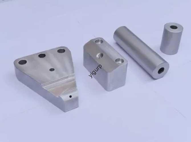
- Mass Production Norm: For most commercial applications (per esempio., staffe automobilistiche, consumer electronics housings), the practical minimum wall thickness ranges from 1.0mm to 1.5mm. This range balances thin-wall benefits (leggero, risparmio di materiale) with process stability (low defect rates).
2. 7 Key Factors That Determine the Minimum Wall Thickness
The actual minimum wall thickness you can achieve isn’t just about hitting a number—it depends on 7 interrelated factors. The table below breaks down each factor, its impact, and practical design adjustments:
| Influencing Factor | Key Impact on Minimum Wall Thickness | Design Adjustments for Thin Walls |
| 1. Casting Area | Larger surface areas require thicker walls. A part with a 100 cm² area needs a minimum thickness of 1.2mm (contro. 0.8mm for a 10 cm² part). | – Keep surface areas of ultra-thin sections (≤1 mm) piccolo (<20 cm²).- Use gradual thickness transitions (slope 1:5) between small thin sections and larger thick sections. |
| 2. Structural Complexity | Parts with deep cavities (>5profondità mm), narrow slits (<1larghezza mm), or complex undercuts need thicker walls. These features disrupt molten metal flow, increasing the risk of cold barriers. | – Avoid deep cavities in ultra-thin sections; if necessary, add diversion ribs (0.8mm di spessore) to guide flow.- Replace narrow slits with wider openings (≥1.5mm) in thin-wall designs. |
| 3. Forza & Functional Requirements | Parts under mechanical load (per esempio., automotive suspension brackets) can’t rely solely on thin walls—they need stiffeners to compensate for strength loss. | – For thin walls (1.0–1.2mm), add stiffeners with a height-to-thickness ratio of 3:1 (per esempio., 3mm tall stiffeners for 1mm walls).- Avoid using thin walls in load-bearing areas; increase thickness to 1.5–2.0mm for critical stress points. |
| 4. Process Feasibility | Thin walls demand stricter control over die casting parameters (per esempio., temperatura, injection speed). Even small deviations can cause defects. | – For walls ≤1.0mm, use high injection speeds (4–5m/s) to fill cavities before solidification.- Preheat molds to 220–250°C (higher than standard 200°C) to slow cooling of thin sections. |
| 5. Surface Treatment Needs | If parts require electroplating, anodizzazione, o lavorazioni meccaniche di precisione, you need to reserve processing allowance (typically 0.1–0.2mm per side). Thin walls without allowance may be damaged during post-treatment. | – For parts needing plating, set minimum wall thickness to ≥1.2mm (to accommodate 0.2mm total allowance).- Ensure wall thickness uniformity (tolerance ±0.1mm) to avoid uneven plating or machining. |
| 6. Aluminum Alloy Type | Different aluminum alloys have varying flowability, which affects their ability to fill thin cavities. | – Use high-flow alloys (per esempio., ADC12, with silicon content 9.5–12%) for thin walls (≤1.0mm).- Avoid low-flow alloys (per esempio., 6061, with high magnesium content) for ultra-thin designs—they’re prone to filling defects. |
| 7. Muffa & Capacità dell'attrezzatura | Modern high-performance die casting machines (per esempio., 600-ton+ cold chamber machines) with precise parameter control can achieve thinner walls than older equipment. | – For walls ≤0.8mm, use machines with closed-loop pressure control (accuracy ±1MPa) and real-time flow monitoring.- Opt for molds with polished cavities (Ra ≤0.8μm) to reduce friction and improve metal flow in thin sections. |
3. Practical Design Guidelines: Balancing Thinness & Prestazione
To help you apply these factors to real projects, here’s a step-by-step design framework for determining the minimum wall thickness:
Fare un passo 1: Define Part Size & Surface Area
Use the table below to set an initial minimum thickness based on part surface area:
| Part Surface Area | Initial Minimum Wall Thickness (ADC12 Alloy) |
| ≤10 cm² (piccole parti: per esempio., alloggiamenti dei sensori) | 0.8–1,0 mm |
| 10–50 cm² (parti medie: per esempio., power adapter enclosures) | 1.0–1.2mm |
| >50 cm² (parti di grandi dimensioni: per esempio., pannelli delle porte automobilistiche) | 1.2–1.5mm |
Fare un passo 2: Adjust for Structural Complexity
- Add 0.2–0.3mm to the initial thickness if the part has:
- Cavità profonde (depth >5mm)
- Narrow slits (larghezza <1.5mm)
- Più di 2 sottosquadri
- No adjustment needed for simple structures (superfici piane, no hidden features).
Fare un passo 3: Account for Functional Needs
- For non-load-bearing parts (per esempio., rifinitura decorativa): Keep the adjusted thickness (from Step 2) — no extra increase needed.
- For load-bearing parts (per esempio., bracket supports): Add 0.3–0.5mm to the adjusted thickness to ensure strength.
- For parts needing surface treatment: Add 0.2mm (total processing allowance) to the final thickness.
Fare un passo 4: Validate with Prototype Testing
Even the best calculations need real-world verification. Produce 10–20 prototype parts with your designed thickness, Poi:
- Verificare la presenza di difetti (undercasting, cold barriers) via visual inspection and X-ray testing.
- Test mechanical performance (resistenza alla trazione, resistenza agli urti) to ensure it meets requirements.
- Adjust thickness by ±0.1mm if defects or performance gaps exist.
4. Common Mistakes to Avoid in Thin-Wall Design
Designing ultra-thin aluminum die cast parts is fraught with pitfalls. Below are 3 frequent mistakes and how to avoid them:
Errore 1: Pursuing “Too Thin” Without Considering Process Limits
- Problema: Designing a 0.6mm wall for a large part (surface area 50 cm²) leads to 80% scrap rates due to undercasting.
- Aggiustare: Stick to the 0.5mm theoretical limit only for small, parti semplici. Per pezzi di grandi dimensioni, use the 1.2–1.5mm practical minimum.
Errore 2: Ignoring Thickness Uniformity
- Problema: A part with 1.0mm walls in one section and 2.0mm walls in another causes uneven cooling, leading to shrinkage sinks.
- Aggiustare: Keep thickness variation within ±20% (per esempio., 1.0mm to 1.2mm, not 1.0mm to 2.0mm). Use gradual transitions to connect different thicknesses.
Errore 3: Forgetting Stiffeners in Thin-Wall Load-Bearing Parts
- Problema: A 1.0mm thick automotive bracket bends under load because it lacks stiffeners.
- Aggiustare: Add stiffeners (height = 3× wall thickness) along the direction of the load. For a 1.0mm wall, 3mm tall stiffeners will double the part’s bending resistance.
5. Yigu Technology’s Perspective on Aluminum Alloy Die Casting Thin-Wall Design
Alla tecnologia Yigu, we believe thin-wall aluminum die casting is about “precision, not just thinness.” For high-end electronics clients needing 0.8mm thin parts (per esempio., 5G sensor housings), our 600-ton cold chamber machines (equipped with real-time flow control) raggiungere 98% yield rates by optimizing injection speed (4.5SM) and mold temperature (240°C). Per i clienti del settore automobilistico, we balance thinness with strength—designing 1.2mm walls with integrated stiffeners that reduce part weight by 15% while meeting crash safety standards.
We’re advancing two key solutions: 1) AI-driven thickness simulation (predicts filling defects before mold production, cutting prototype time by 40%); 2) High-flow aluminum alloys (custom-blended with 11% silicio) that improve flowability for 0.7mm thin sections. Our goal is to help clients unlock the benefits of thin-wall design—lightweight, risparmio di materiale, and faster cooling—without sacrificing quality or performance.
Domande frequenti
- Can I achieve a 0.4mm wall thickness for aluminum alloy die casting?
No—0.4mm is below the theoretical limit of 0.5mm for aluminum alloys. Even with advanced equipment, molten aluminum will solidify before filling a 0.4mm cavity, portando a 100% scrap rates. For ultra-thin applications, consider zinc die casting (which can achieve 0.3mm walls) or post-processing methods like machining.
- How does wall thickness affect the cost of aluminum die cast parts?
Thinner walls reduce material costs (per esempio., a 1.0mm part uses 30% less aluminum than a 1.5mm part of the same size) but may increase process costs (stricter parameter control, higher defect rates if not optimized). Per la produzione di massa (>100,000 parti), the material savings usually offset the process costs—making 1.0–1.2mm walls the most cost-effective range.
- Do different aluminum alloys have different minimum wall thickness limits?
Yes—high-flow alloys like ADC12 (silicon-rich) can achieve thinner walls (0.55mm) than low-flow alloys like 6061 (magnesium-rich), which have a practical minimum of 1.0mm. When designing, always check the alloy’s flowability data (forniti dai fornitori) to set realistic thickness limits.