If you’re wondering what the milling machining process È, in poche parole: è una tecnica di produzione sottrattiva che utilizza utensili da taglio rotanti (chiamate frese, frese per facciate, o tagliamosche) per rimuovere materiale da un pezzo, modellandolo in modo preciso, parti personalizzate. A differenza della perforazione (che crea solo buchi), la fresatura può produrre superfici piane, slot, ingranaggi, contorni, and even 3D shapes—making it one of the most versatile processes in manufacturing, used in industries from aerospace to automotive to consumer electronics.
Core Principles of the Milling Machining Process
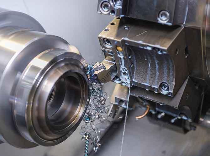
Nel suo cuore, milling relies on two key motions working together: IL rotation of the cutting tool (primary motion) e il movement of the workpiece (feed motion) against the tool. The cutting tool’s sharp edges shear away material as it spins, while the workpiece (held in a vise or fixture on a table) moves along one or more axes (X, Y, Z, and sometimes more for complex jobs) to control the depth, larghezza, and shape of the cut.
A critical principle here is compatibilità dei materiali: not all cutting tools work for all materials. Per esempio, acciaio rapido (HSS) tools are cost-effective for aluminum or plastic, but carbide tools are necessary for hard metals like titanium or stainless steel—they resist heat better and last 5–10 times longer (a fact backed by machining industry data).
Esempio del mondo reale
A small automotive parts shop I worked with once struggled with inconsistent slot cuts in aluminum brackets. After reviewing their process, we realized they were using a carbide tool meant for steel (too rigid for aluminum) at the wrong speed. Switching to an HSS endmill and adjusting the spindle speed from 1,500 RPM to 3,000 giri al minuto (the recommended range for aluminum) eliminated the issue—reducing scrap rates by 30% in the first month.
Key Components of a Milling System
To execute the milling process effectively, you need three core components. The table below breaks down their roles, common types, and why they matter:
| Component | Primary Function | Common Types | Critical Considerations |
| Milling Machine | Provides power for tool rotation and workpiece movement | Vertical Milling Machine (tool moves up/down), Horizontal Milling Machine (tool spins horizontally) | Vertical mills are better for 2D/3D shapes; horizontal mills excel at deep slots or gear cutting. |
| Cutting Tool | Removes material from the workpiece | Endmill (for slots/3D shapes), Face Mill (per superfici piane), Ball Nose Cutter (for contours) | Tool material (HSS vs. carburo) and number of flutes (2–8) affect speed and finish quality. |
| Workholding Fixture | Secures the workpiece to prevent movement | Vise (per piccole parti), Morsetti (per pezzi di grandi dimensioni), Custom Jigs (for repeatable jobs) | Poor fixturing causes vibration—leading to rough surfaces or broken tools. |
Common Types of Milling Operations
IL milling machining process isn’t one-size-fits-all—you choose an operation based on the part you need to make. Here are the four most widely used, with practical use cases:
1. Fresatura frontale
This operation creates flat, smooth surfaces on the top or bottom of a workpiece. The face mill (a circular tool with cutting edges on its face) spins, and the workpiece moves across it.
- Use Case: A manufacturer making engine blocks uses face milling to flatten the surface where the cylinder head attaches—ensuring a tight seal to prevent oil leaks.
2. Peripheral Milling (Slotting)
Here, the cutting tool’s side edges (not just the face) remove material, creating slots, scanalature, or external contours.
- Use Case: A furniture maker uses peripheral milling to cut slots in wooden table legs, so metal braces can fit snugly and reinforce the structure.
3. 3-Fresatura degli assi
The workpiece moves along three axes (X: sinistra/destra, Y: avanti/indietro, Z: su/giù), while the tool rotates. This is the most common type for small to medium parts.
- Use Case: A medical device company uses 3-axis milling to produce plastic inhaler components, which require precise 2D+ depth cuts.
4. 5-Fresatura degli assi
For complex, parti curve, 5-axis mills add rotation around two more axes (UN: tilts the table, B: rotates the table). This lets the tool reach hard-to-access areas without repositioning the workpiece.
- Use Case: Aerospace manufacturers rely on 5-axis milling to make turbine blades—their curved shapes and thin walls demand precision that 3-axis machines can’t match.
Step-by-Step Guide to Executing a Milling Job
While every project varies, a standard milling workflow ensures consistency and quality. Below is a actionable, step-by-step process used by professional machinists:
- Design the Part (CAD): Start with a 2D or 3D computer-aided design (CAD) file (per esempio., using SolidWorks or AutoCAD). This file defines the part’s dimensions, tolleranze (per esempio., ±0.001 inches for precision parts), and features.
- Select Materials & Utensili: Choose the workpiece material (alluminio, acciaio, plastica) and matching cutting tool. Per esempio:
- Aluminum → HSS endmill (2–4 flutes)
- Stainless steel → Carbide endmill (4–6 flutes)
- Set Up the Machine: Mount the workpiece in a fixture (per esempio., a vise) on the mill table. Align the workpiece using a dial indicator to ensure it’s straight (this prevents off-center cuts).
- Program the Machine (CAMMA): Convert the CAD file to a computer-aided manufacturing (CAMMA) programma. The CAM software generates G-code (the language mills understand) that tells the machine how fast to spin the tool (velocità del mandrino) and how fast to move the workpiece (velocità di avanzamento).
- Pro Tip: For beginners, use CAM software with presets—many include recommended speeds/feeds for common materials (per esempio., 2,500 RPM for aluminum with an HSS tool).
- Test the Cut: Run a “dry run” (no material) first to check if the tool path is correct. Then make a test cut on a scrap piece of the same material to verify dimensions and surface finish.
- Execute the Full Job: Once the test cut passes, run the program for the actual workpiece. Monitor the process for vibration or unusual noises—these are signs of a problem (per esempio., loose fixturing).
- Inspect the Final Part: Use tools like calipers, micrometri, or coordinate measuring machines (CMM) to check if the part meets the CAD specifications. If not, adjust the CAM program (per esempio., tweak feed rate) and retry.
Critical Factors That Impact Milling Quality & Efficienza
Even with the right equipment, poor choices here can ruin parts or slow down production. Focus on these four factors:
1. Velocità del mandrino & Tasso di avanzamento
These two parameters are inseparable. Velocità del mandrino (giri al minuto) is how fast the tool spins; velocità di avanzamento (IPM, inches per minute) is how fast the workpiece moves.
- Data Backed: According to the Machinist’s Handbook, a carbide endmill cutting steel (1018 grado) should run at 1,200–1,500 RPM with a feed rate of 10–15 IPM. Running too fast (per esempio., 2,000 giri al minuto) overheats the tool; troppo lento (per esempio., 800 giri al minuto) leaves rough surfaces.
2. Cutting Fluid
Cutting fluid (oil or water-based) cools the tool and workpiece, riduce l'attrito, e lava via i trucioli.
- When to Use It: Mandatory for hard metals (acciaio, titanio) to prevent tool wear. Optional for aluminum (but still recommended for better finish).
3. Tool Maintenance
Dull tools cause:
- Increased scrap rates (parts don’t meet dimensions)
- Longer cycle times (the tool has to work harder)
- Machine damage (excess vibration strains the mill).
- Best Practice: Inspect tools after every 10–20 parts. Replace HSS tools when edges are chipped; regrind carbide tools (they can be sharpened 3–5 times before needing replacement).
4. Workpiece Material Hardness
Harder materials (per esempio., titanio, Rockwell hardness 35–40 HRC) require slower speeds, carbide tools, and more rigid machines. Softer materials (per esempio., alluminio, Rockwell 20–25 HRC) can handle faster speeds and cheaper HSS tools.
Yigu Technology’s Perspective on Milling Machining Process
Alla tecnologia Yigu, we see the milling machining process as the backbone of precision manufacturing—especially as industries demand smaller, more complex parts (like those in electric vehicles or medical devices). Over the years, we’ve noticed a key trend: the shift from manual 3-axis milling to automated 5-axis systems. This isn’t just about speed; it’s about consistency. Automated mills reduce human error, cut scrap rates by up to 40%, and let manufacturers take on jobs that were once too complex (per esempio., 3D-printed metal part finishing). We also advise clients to prioritize tool-material matching—investing in carbide tools for hard metals might cost more upfront, but it saves money long-term by reducing tool changes and downtime.
FAQ About Milling Machining Process
1. What’s the difference between milling and turning?
Milling uses a rotating cutting tool and moving workpiece to shape parts (versatile for 2D/3D shapes). Turning uses a rotating workpiece and stationary cutting tool (best for cylindrical parts like bolts or shafts).
2. How accurate is the milling machining process?
Modern CNC mills can achieve tolerances as tight as ±0.0001 inches (2.54 micrometri)—critical for industries like aerospace, where even tiny errors can cause failures.
3. Can milling be used for plastic parts?
SÌ! Milling is ideal for plastic (per esempio., ABS, policarbonato) because it creates smooth surfaces without melting the material (as long as you use the right speed: 3,000–5,000 RPM for HSS tools).
4. What’s the cost of a milling machine for small businesses?
Entry-level 3-axis CNC mills start at \(10,000–)20,000. Used machines can cost \(5,000–)10,000, making them accessible for small shops.
5. How long does it take to learn the milling process?
Basic manual milling takes 1–2 months to master. Fresatura CNC (including CAD/CAM software) takes 3–6 months of practice to produce high-quality parts consistently.