A high-performance CNC machining wall breaker prototype is a cornerstone of product development—it validates structural rationality, testa le funzioni principali (come la frantumazione ad alta velocità e l'impermeabilizzazione), e riduce al minimo i rischi prima della produzione di massa. Questo articolo analizza sistematicamente l'intero processo di sviluppo, dalla progettazione al collaudo, utilizzando confronti basati sui dati, linee guida passo passo, e soluzioni pratiche per affrontare le sfide principali.
1. Preparazione preliminare: Lay the Groundwork for Prototype Precision
Preliminary preparation directly impacts the prototype’s accuracy and functionality. It focuses on two critical tasks: 3Modellazione D & structural optimization E selezione del materiale, both tailored to the unique demands of wall breakers (per esempio., high-speed rotation, sicurezza alimentare).
1.1 3Modellazione D & Structural Optimization
Use professional CAD software (per esempio., SolidWorks, UG) to create a detailed 3D model of the wall breaker. The model must cover all components and prioritize structural optimization to avoid machining errors:
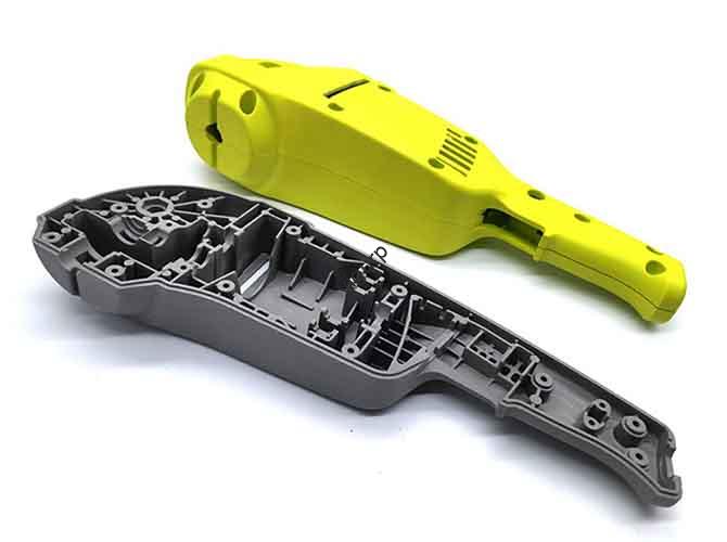
- Component Breakdown: Split the machine into parts like the cup body, montaggio della lama, motor base, control panel, E sealing ring for easier machining and assembly.
- Key Optimization Focus Areas:
- Blade Layout: Design blade angles (15–20°) and distribution to ensure efficient crushing of hard ingredients (per esempio., noci, bones).
- Sealing Structure: Precisely design the groove for the silicone sealing ring (tolleranza: ±0,05 mm) to prevent liquid leakage during high-speed rotation.
- Assembly Compatibility: Mark positions of buckles, screw holes, and positioning grooves to ensure components fit securely (per esempio., cup body locks tightly to the base).
Why optimize these structures? Poor blade layout can reduce crushing efficiency by 30%, while a flawed sealing design may cause leakage—leading to rework that adds 2–3 days to the timeline.
1.2 Selezione dei materiali: Match Materials to Component Functions
Different components of the wall breaker require materials with specific properties (per esempio., wear resistance for blades, transparency for cup bodies). The table below compares the most suitable materials:
| Tipo materiale | Vantaggi principali | Ideal Components | Fascia di costo (al kg) | Lavorabilità |
| ABS/PC Plastic | Easy to cut, basso costo, simulates injection molding texture | Cup body, body shell, handle (non-load-bearing parts) | \(2–)5 | Eccellente (fast cutting, low tool wear) |
| Lega di alluminio | Alta resistenza, good heat dissipation, durevole | Motor base, blade brackets (load-bearing/heat-generating parts) | \(7–)12 | Bene (requires anodizing for rust resistance) |
| Acciaio inossidabile (304/316) | Elevata durezza, resistente alla corrosione, sicuro per gli alimenti | Blades, high-wear components (contacts food/ingredients) | \(15–)20 | Moderare (needs EDM for sharp edges) |
| Resin Compound | Basso costo, fast reproduction of complex shapes | Small-batch replica parts (paired with CNC-machined molds) | \(10–)14 | Moderare (not suitable for standalone structural parts) |
Esempio: The cup body, which needs transparency for ingredient observation, usi PC plastic. Blades, requiring wear resistance and food safety, are made of 304 acciaio inossidabile.
2. Processo di lavorazione CNC: Turn Design into Physical Components
The CNC machining phase follows a linear workflow—model slicing & programming → billet preparation → rough machining → finishing—with special attention to wall breaker-specific structures (per esempio., curved cup inner walls, sharp blades).
2.1 Model Slicing & Programmazione
Import the 3D model into CAM software (per esempio., Mastercam, PowerMill) to generate toolpaths and G-code. Key steps include:
- Cutting Parameter Setting (by Material):
- Plastica ABS: Cutting speed = 1800–2200 rpm; Feed rate = 600–800 mm/min.
- Lega di alluminio: Cutting speed = 1000–1500 rpm; Feed rate = 400–600 mm/min (use coolant to prevent sticking).
- Acciaio inossidabile: Cutting speed = 800–1000 rpm; Feed rate = 200–300 mm/min (slower speed for hardness).
- Selezione dello strumento:
- For curved surfaces (cup inner wall): Utilizzo ball end mills (Φ3–5mm) to ensure smoothness.
- For blades: Utilizzo carbide tools or wire EDM to achieve sharp edges (tolleranza: ±0,05 mm).
- For heat dissipation holes: Utilizzo hollow tools or EDM for complex hole shapes (ensures uniform heat flow).
- Multi-Axis Linkage: Use a five-axis machine tool for complex components (per esempio., blade brackets) to avoid tool interference and ensure precision.
2.2 Esecuzione della lavorazione: Passaggi chiave & Precautions
Proper execution ensures component accuracy. Follow this sequence:
- Billet Preparation: Cut raw materials into billets matching component sizes (per esempio., ABS blocks for cup bodies, aluminum sheets for motor bases) and reserve 0.5–1mm machining allowance.
- Clamping: Secure billets to the machine table—use vacuum adsorption for plastic parts (prevents deformation) and three-jaw chucks for metal parts (ensures stability).
- Lavorazione grezza: Use large-diameter tools (Φ8–10mm) to remove 80–90% of excess material quickly (salva 30% of machining time).
- Finitura: Use small-diameter tools (Φ0.5–2mm) to refine details (per esempio., blade edges, fori filettati) and achieve surface roughness Ra <0.8μm for visible parts.
Critical Precaution: Replace worn tools immediately—dull tools can increase dimensional error by 0.2mm, ruining blade sharpness or sealing groove precision.
3. Post-elaborazione: Enhance Appearance & Funzionalità
Post-processing removes machining flaws and prepares components for assembly. It includes trattamento superficiale, serigrafia, E pre-assembly checks.
3.1 Trattamento superficiale: Improve Durability & Estetica
Choose treatment methods based on material and component function:
- Plastic Parts (Cup Body, Shell):
- Levigatura (200–800 grit sandpaper) to remove tool marks.
- Sandblasting to simulate injection molding texture.
- Spraying food-grade paint (per esempio., matte UV paint) per la resistenza ai graffi.
- Metal Parts (Motor Base, Blades):
- Lega di alluminio: Anodizzazione (matte/silver finish) per prevenire la ruggine.
- Acciaio inossidabile: Polishing to achieve a smooth, food-safe surface.
3.2 Silk Screen Printing & Pre-Assembly Checks
- Silk Screen Printing: Print brand logos, operation instructions (per esempio., “High Speed,” “Smoothie,” “Pulito”), and safety warnings (per esempio., “Do Not Touch Blades”) using high-temperature, wear-resistant ink.
- Pre-Assembly Checks:
- Verify dimensions with calipers (per esempio., cup body capacity, sealing groove size).
- Test blade sharpness (use a sample ingredient to check crushing fineness).
- Inspect surface quality (no scratches, paint chips, or ink smudges).
4. Assemblea & Test: Validate Prototype Performance
Assembly and testing confirm the prototype meets design standards for functionality, sicurezza, e durata.
4.1 Step-by-Step Assembly
- Attach the motor base (lega di alluminio) to the body shell using M3 screws (coppia: 1.5–2.0 N·m).
- Install the montaggio della lama into the motor base (ensure it rotates freely without jitter).
- Fit the silicone sealing ring into the cup body’s groove (press firmly to secure).
- Mount the control panel onto the body shell (align buttons with internal circuits).
- Lock the cup body to the base (test the buckle for secure attachment).
4.2 Testing Checklist: Ensure Reliability
Test the prototype in three key areas:
| Test Category | Tools/Methods | Pass Criteria |
| Functional Test | Speed meter, water test | – Blades rotate at 20,000–30,000 rpm (meets crushing requirements).- No water leakage during 5-minute high-speed operation.- Buttons respond correctly (per esempio., “Stop” halts rotation immediately). |
| Structural Test | Pull test, temperature monitor | – Handle resists 5kg pull force without loosening.- Motor base temperature <60°C after 30-minute operation (good heat dissipation). |
| Appearance Test | Ispezione visiva, gloss meter | – No scratches, paint defects, or smudged logos.- Consistent color (no visible aberration between components). |
La prospettiva della tecnologia Yigu
Alla tecnologia Yigu, we view CNC machining wall breaker prototypes as a “design validator”—they bridge ideas and mass production while cutting risks. Our team prioritizes two core aspects: precision and safety. For critical parts like blades, usiamo 304 stainless steel and EDM to ensure sharpness and food safety. For sealing structures, we control tolerance to ±0.03mm (tighter than industry standards) to eliminate leakage. We also integrate 3D scanning post-machining to verify dimensional accuracy. By focusing on these details, we help clients reduce post-production defects by 25–30% and accelerate time-to-market by 1–2 weeks. Whether you need an appearance prototype for exhibitions or a functional one for testing, we tailor solutions to your goals.
Domande frequenti
- Q: How long does it take to produce a CNC machining wall breaker prototype?
UN: Typically 8–10 days. This includes 1–2 days for 3D modeling, 2–3 days for CNC machining, 1–2 days for post-processing, and 2–3 days for assembly and testing.
- Q: Can I use resin instead of ABS/PC plastic for the cup body?
UN: Resin is not ideal. While it’s cheap and easy to cast, it has low impact resistance—high-speed rotation vibrations may cause it to crack. ABS/PC plastic is better for its durability and machinability.
- Q: What should I do if the prototype leaks during the water test?
UN: Primo, check the silicone sealing ring (replace if damaged). If the ring is intact, verify the sealing groove size (tolerance should be ±0.05mm). If the groove is too large, add a thin food-grade silicone pad to the cup body—this fix takes 1–2 hours and resolves most leakage issues.