Il tornio a fantina mobile ad alta precisione rappresenta una svolta nella lavorazione di piccole dimensioni, parti complesse: pensa a componenti piccolissimi 0.5 mm di diametro con tolleranze strette fino a ±0,001 mm. A differenza dei torni convenzionali, it uses a boccola di guida to support the workpiece, riducendo al minimo le vibrazioni e consentendo una precisione senza pari. Che tu stia producendo aghi medici o dispositivi di fissaggio per il settore aerospaziale, mastering the Swiss-type lathe machining model is key to producing consistent, parti di alta qualità. This guide breaks down every critical aspect, from machine structure to real-world applications, to help you avoid common mistakes and maximize efficiency.
1. Machine Structure and Components: The Backbone of Precision
A Swiss-type lathe’s unique design is what sets its precision apart. Every component works together to keep the workpiece stable and the cutting process controlled. Here’s a detailed look at the core parts:
| Componente | Funzione | Key Precision Features |
| Swiss-type lathe (Main Body) | Houses all components; provides a stable base for machining. | Heavy-duty cast iron frame reduces vibration (vibration amplitude ≤0.0005 mm). |
| Mandrino | Rotates the workpiece at high speeds. | High-speed spindle (fino a 10,000 giri/min) with runout ≤0.0003 mm; ensures uniform rotation. |
| Guide bushing | Supports the workpiece near the cutting tool (the “secret” to Swiss-type precision). | Precision-ground bushing (inner diameter tolerance ±0.0002 mm); minimizes workpiece deflection. |
| Tool turret | Holds multiple cutting tools (girando, fresatura, perforazione) for quick changes. | 8-12 station turret with tool positioning accuracy ±0.0005 mm; riduce il tempo di configurazione. |
| Contropunta | Supports the far end of long workpieces (per esempio., 300 mm shafts). | Adjustable tailstock center with concentricity ≤0.0005 mm; prevents workpiece bending. |
| Slide system | Moves the tool turret or workpiece along X, Y, Assi Z. | Linear guideways (instead of dovetail slides) with positioning accuracy ±0.0002 mm; liscio, precise movement. |
Quick Analogy: Think of the boccola di guida as training wheels for a bike—it keeps the workpiece (like a bike) stable when moving fast, so the cutting tool (like a rider) can make precise “turns” without wobbling. Senza di esso, lungo, thin workpieces would bend, ruining accuracy.
2. Machining Processes and Techniques: Turning Small Parts with Big Precision
Swiss-type lathes excel at “done-in-one” machining—completing all operations (girando, fresatura, perforazione) in un unico allestimento. This eliminates errors from repositioning the workpiece. Below are the key processes and how to use them effectively:
Core Processes & Migliori pratiche
- Girando: The primary process for shaping cylindrical surfaces (per esempio., alberi, perni).
Mancia: Utilizzare acciaio ad alta velocità (HSS) or carbide inserts. For stainless steel parts (common in medical devices), set spindle speed to 5,000-8,000 rpm and feed rate to 0.01-0.02 mm/rev—this reduces tool wear and ensures a smooth surface.
- Fresatura: Adds flat or angled features (per esempio., slots in electronic connectors).
Mancia: Use a live tool turret (rotates the milling tool) for 4-axis machining. For small slots (larghezza <1 mm), utilizzare un 0.8 mm diameter end mill and cut in 0.1 mm depth increments to avoid breaking the tool.
- Perforazione: Creates small holes (fino a 0.1 diametro mm) in parts like fuel injector nozzles.
Mancia: Use carbide drills with a 135° point angle—they cut cleanly without wandering. Add a coolant mist system to keep the drill cool (prevents overheating and breakage).
- Filettatura: Produces precise threads (per esempio., M1.0 x 0.25 threads for electronics).
Mancia: Use single-point threading tools. For fine threads, set spindle speed to 3,000-4,000 rpm and thread depth to 0.613 x pitch (per ISO standards) to avoid thread damage.
- Parting: Cuts the finished part from the raw material bar.
Mancia: Use a parting tool with a width equal to 1.5x the workpiece diameter. Per un 5 mm diameter part, utilizzare un 7.5 mm wide tool—this prevents the part from “pinching” the tool during cutting.
- Rettifica: Optional process for ultra-smooth surfaces (per esempio., bearing races with Ra ≤0.02 μm).
Mancia: Use a built-in grinding spindle (if your lathe has one). Set grinding wheel speed to 12,000 rpm and feed rate to 0.005 mm/rev for best results.
Caso di studio: A medical device manufacturer needed to make a 2 mm diameter needle with a 0.5 mm hole and Ra 0.1 μm surface finish. Using a Swiss-type lathe, they: 1) Turned the outer diameter (velocità del mandrino 8,000 giri/min); 2) Drilled the hole (carbide drill, 6,000 giri/min); 3) Ground the surface (12,000 giri/min). All operations were done in one setup, con il risultato di 99.5% parte (tasso di passaggio)—up from 85% with conventional lathes.
3. Precision Control and Measurement: Keeping Tolerances Tight
In Swiss-type lathe machining, even a 0.001 mm error can make a part useless (per esempio., a medical needle that’s too thick won’t fit in a syringe). Controllo di precisione and measurement are non-negotiable. Here’s how to ensure your parts meet specs:
Key Control & Measurement Steps
| Aspetto | Actions to Take | Tools Used |
| Tolleranza | Set tolerances based on part use: – Dispositivi medici: ±0.0005-±0.001 mm – Elementi di fissaggio aerospaziali: ±0.001-±0.002 mm – Elettronica: ±0.002-±0.005 mm | Follow ISO 286-1 (tolerance standard) to define limits. |
| Precisione | Calibrate the lathe monthly: – Check spindle runout with a dial indicator – Verify slide positioning with a laser interferometer – Adjust guide bushing concentricity if needed | Interferometro laser (accuracy ±0.0001 mm); dial indicator (risoluzione 0.0001 mm). |
| Finitura superficiale | Monitor Ra value during machining: – For functional parts: Ra 0.2-1.6 µm – For appearance parts: Ra 0.02-0.2 µm | Surface roughness meter (risoluzione 0.001 µm); check every 10 parti. |
| Controllo di qualità | Implement in-process inspection: – Dopo aver girato: Check outer diameter with a micrometer – Dopo la perforazione: Verify hole size with a pin gauge – After final machining: Do a full inspection with a CMM | Micrometro digitale (accuracy ±0.0001 mm); calibri a spillo (tolerance ±0.0002 mm); Macchina di misura a coordinate (CMM) (3D accuracy ±0.0005 mm). |
Domanda: Why do my parts have inconsistent tolerances (some ±0.001 mm, some ±0.002 mm)?
Risposta: Most likely, IL boccola di guida is worn or dirty. Clean the bushing with a lint-free cloth and check its inner diameter—if it’s worn by 0.0005 mm or more, replace it. Anche, ensure the workpiece bar is straight (deflection ≤0.001 mm/m) — bent bars cause uneven cutting.
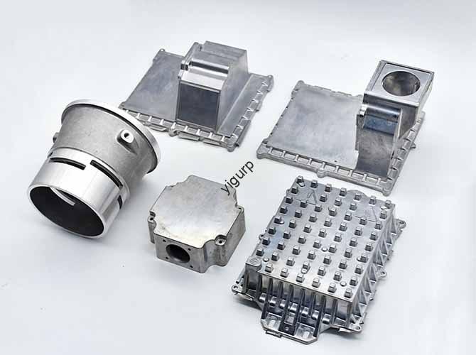
4. Applications and Industries: Where Swiss-Type Lathes Shine
Swiss-type lathes are the go-to for small, parti di alta precisione. Their ability to handle complex operations in one setup makes them indispensable in these industries:
Industry-Specific Uses
- Dispositivi medici: Machines parts like hypodermic needles (0.5-2 diametro mm), impianti dentali (tolleranza ±0,001 mm), and surgical tool components. The guide bushing ensures parts are straight and precise—critical for patient safety.
- Aerospaziale: Produces small fasteners (per esempio., M2 x 0.4 discussioni), ugelli degli iniettori di carburante (0.1 fori da mm), e componenti del sensore. Tolerances as tight as ±0.0005 mm ensure parts work in extreme conditions (high altitude, temperatura).
- Elettronica: Makes connector pins (1-3 diametro mm), componenti del circuito, and smartphone camera parts. The “done-in-one” process reduces lead time—key for fast-paced electronics manufacturing.
- Automobilistico: Creates fuel system parts (per esempio., steli delle valvole), componenti di trasmissione, and sensor pins. Produzione in grandi volumi (fino a 10,000 parti/giorno) is possible with Swiss-type lathes.
- Industria meccanica: Builds precision gears (module ≤0.5), piccoli alberi, and bearing races. The slide system’s accuracy ensures gear teeth mesh perfectly.
- Strumenti di precisione: Makes watch parts (per esempio., balance wheels, 1-2 diametro mm), microscope components, and measuring tool bits. Surface finish Ra ≤0.05 μm is standard for these high-end parts.
Fun Fact: A single Swiss-type lathe can make 5,000-10,000 small parts per day—enough to supply 10,000 smartphones with connector pins or 5,000 medical syringes with needles.
5. Software and Simulation: Optimizing Before Cutting
Modern Swiss-type lathes rely on software to streamline programming and avoid costly mistakes. Software CAD/CAM and simulation tools let you test the machining process virtually—no need to waste material on trial runs.
Key Software Tools & Their Roles
| Software Type | Scopo | Esempi | Vantaggi |
| CAD (Progettazione assistita da computer) | Creates 3D models of the part. | SolidWorks, Fusione 360 | Lets you design complex features (per esempio., 0.1 mm slots) with precise dimensions; exports files to CAM software. |
| CAMMA (Produzione assistita da computer) | Converts CAD models into machine-readable code (Codice G). | Mastercam svizzero, GibbsCAM | Automatically generates toolpaths for turning, fresatura, perforazione; ottimizza i parametri di taglio (velocità del mandrino, velocità di avanzamento). |
| Software di simulazione | Tests the machining process virtually. | Vericut, NX CAM Simulation | Catches collisions (per esempio., tool hitting guide bushing), identifies inefficient toolpaths, and predicts part accuracy. |
| Programmazione | Edits G-code (se necessario) for custom operations. | Mach3, Fanuc Manual Guide i | Allows fine-tuning of toolpaths (per esempio., adjusting thread depth for hard materials). |
How to Use Software for Better Results
- Fare un passo 1: Design with CAD: Create a 3D model of the part, adding all features (buchi, slot, discussioni) with exact tolerances (per esempio., ±0.001 mm for a medical needle).
- Fare un passo 2: Generate Toolpaths with CAM: Import the CAD model into CAM software. Select the Swiss-type lathe as the machine, then choose the processes (turning → drilling → milling). The software will generate G-code.
- Fare un passo 3: Simulate: Run the G-code in simulation software. Controlla:
- Collisioni (per esempio., milling tool hitting tailstock)
- Short shots (per esempio., drill not reaching full depth)
- Overcuts (per esempio., turning tool removing too much material)
- Fare un passo 4: Adjust and Run: Fix any issues in the simulation (per esempio., reposition the tool), then send the G-code to the lathe.
Esempio: A manufacturer was struggling with broken drills when making 0.2 fori da mm. They used simulation software and found the drill was moving too fast (velocità di avanzamento 0.02 mm/giro). By reducing the feed rate to 0.005 mm/rev in the CAM software, they eliminated drill breakage—saving $5,000/month in tool costs.
Yigu Technology’s View
Alla tecnologia Yigu, we believe high-precision Swiss-type lathe machining thrives on “synergy”—of stable machine components, smart processes, e software. We equip our Swiss-type lathes with ultra-precise guide bushings (≤0.0002 mm tolerance) and linear guideways for accuracy. For clients in medical/aerospace, we pair CAD/CAM (SolidWorks + Mastercam svizzero) with in-process CMM checks to hit ±0.0005 mm tolerances. We also train teams to optimize toolpaths via simulation, cutting trial runs by 70%. Our goal: turn small, complex part challenges into reliable, soluzioni economicamente vantaggiose.
Domande frequenti
- Q: What’s the difference between a Swiss-type lathe and a conventional lathe?
UN: A Swiss-type lathe uses a boccola di guida to support the workpiece near the cutting tool (ideal for small, long parts ≤20 mm diameter). A conventional lathe holds the workpiece at both ends (better for larger parts >20 diametro mm). Swiss-type lathes also offer “done-in-one” machining, while conventional lathes often need multiple setups.
- Q: How to choose the right tool for Swiss-type lathe machining?
UN: Per materiali morbidi (alluminio, plastica), use HSS tools (conveniente, affilato). Per materiali duri (acciaio inossidabile, titanio), use carbide tools (resistente al calore, long-lasting). For tiny features (≤1 mm), use micro-tools (per esempio., 0.1 punte in metallo duro da mm) with a rigid tool holder to prevent bending.
- Q: Can Swiss-type lathes machine non-cylindrical parts?
UN: SÌ! With a live tool turret and 4/5-axis capability, they can mill flat surfaces, slot, and even 3D features (per esempio., curved medical implant heads). Use CAM software to generate complex toolpaths, and simulation to test for collisions.