Nella produzione industriale, why do automotive and aerospace industries rely on Tornitura CNC for cylindrical parts like engine shafts or fuel nozzles? The answer lies in the CNC turning machining process—a computer-controlled method that transforms raw metal bars into high-precision, componenti uniformi con un errore umano minimo. A differenza della tornitura manuale, che dipende dall'abilità dell'operatore, CNC turning ensures consistent quality across high-volume runs while handling complex geometries. Questo articolo analizza il 6 core stages of the process, parametri chiave, selezione dello strumento, controllo di qualità, e applicazioni nel mondo reale, helping you master every step for efficient, accurate part production.
What Is the CNC Turning Machining Process?
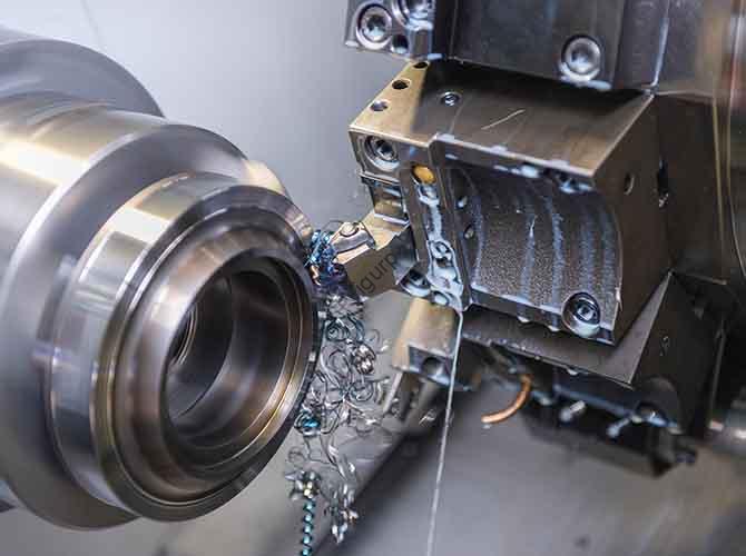
Processo di lavorazione di tornitura CNC is an additive-subtractive manufacturing method that uses Computer Numerical Control (CNC) systems to rotate a workpiece while a cutting tool shapes it into cylindrical or conical forms. The process removes excess material from the workpiece (typically metal bars, 5–100mm in diameter) to create features like outer circles, end faces, scanalature, discussioni, o rastremazioni.
Think of it as a “digital lathe operator”: it follows pre-programmed G-code and M-code to control tool movement, velocità del mandrino, and feed rate—executing repetitive tasks with micron-level accuracy (up to ±0.01mm) E 24/7 coerenza. It’s ideal for producing rotational parts, from small electronic connectors to large industrial shafts.
6 Core Stages of the CNC Turning Machining Process
Il processo segue un percorso lineare, error-proof workflow—each stage builds on the last to ensure part quality. Below is a detailed breakdown of each step, with actionable tips and common pitfalls to avoid:
1. Process Analysis (The Foundation of Success)
Process analysis is the first and most critical step—it defines how the part will be machined. Key tasks include:
- Part Drawing Interpretation: Extract critical details from 2D/3D drawings:
- Dimensional requirements (per esempio., diametro esterno: 20±0,02 mm, lunghezza: 100mm).
- Surface finish standards (per esempio., Ra < 1.6μm for visible areas).
- Material type (per esempio., lega di alluminio 6061, acciaio inossidabile 304).
- Machining Content Selection: Decide which features to machine (per esempio., buchi, discussioni, scanalature) and their order—follow the “from rough to fine” principle (roughing removes 80–90% of excess material first; finishing refines precision).
- Sequence Optimization: Avoid repositioning the workpiece unnecessarily. Per esempio:
- Machine the outer circle → 2. Drill the center hole → 3. Cut threads → 4. Finish the end face.
Pitfall to Avoid: Skipping process analysis leads to tool collisions or out-of-tolerance parts. Per esempio, machining threads before drilling a center hole can cause the workpiece to vibrate, ruining thread accuracy.
2. Selezione dello strumento (Match Tools to Material & Caratteristiche)
The right tool directly impacts machining efficiency and surface quality. Use this table to select tools based on material and feature type:
| Tool Type | Ideal Materials | Key Features Machined | Machinability Tips |
| External Turning Tools | Tutti i metalli (alluminio, acciaio, titanio) | Outer circles, si assottiglia, end faces | – Use carbide inserts (per esempio., CCMT 09T304) for high-speed machining (150–200 m/min for aluminum). – HSS tools (per esempio., W18Cr4V) for low-speed, high-precision finishing. |
| Drilling Tools | Soft metals (alluminio, rame); low-hardness steel (45#) | Through holes, fori ciechi | – Twist drills for small holes (≤10 mm); indexable drills for large holes (>10mm). – Use coolant to reduce heat buildup (prevents drill bit wear). |
| Threading Tools | Acciaio (304, 45#), leghe di alluminio | External threads (per esempio., M10×1.5), internal threads | – Indexable threading inserts (per esempio., 16IR 1.5 ISO) for fast thread cutting. – Single-point threading tools for non-standard thread pitches. |
| Grooving Tools | Tutti i metalli; best for ductile materials (alluminio, ottone) | External grooves (per esempio., snap ring grooves), internal grooves | – Use narrow-blade tools (larghezza: 0.5–5 mm) to avoid material buildup. – Reduce feed rate (0.05–0.1mm/rev) for deep grooves (prevents tool breakage). |
Esempio: Machining M8×1.25 threads on a stainless steel 304 shaft → Choose a 16IR 1.25 ISO threading insert with TiAlN coating (resists wear from stainless steel’s high hardness).
3. Cutting Parameter Setting (Balance Speed, Foraggio, & Profondità)
Cutting parameters (velocità, velocità di avanzamento, depth of cut) determine how fast and accurately the part is machined. Below are optimized parameters for common materials:
| Materiale | Cutting Speed (Vc, m/mio) | Tasso di avanzamento (F, mm/rev) | Depth of Cut (ap, mm) | Key Reasoning |
| Lega di alluminio 6061 | 150–200 | 0.15–0,3 | Roughing: 2–5; Finitura: 0.1–0.5 | Aluminum’s low hardness (HB 60–90) allows high speeds; avoid excessive depth (causes deformation). |
| Acciaio inossidabile 304 | 80–120 | 0.1–0.2 | Roughing: 1–3; Finitura: 0.1–0,3 | Elevata durezza (HB 150–180) requires slower speeds; use coolant to reduce heat (prevents work hardening). |
| Acciaio al carbonio 45# | 120–180 | 0.12–0.25 | Roughing: 1.5–4; Finitura: 0.1–0.4 | Balances speed and tool life; carbide tools work best for high-speed roughing. |
Formula Tip: Calculate spindle speed (N, giri/min) using N = (1000 × Vc) / (π × D), where D = workpiece diameter (mm). Per esempio, a 20mm aluminum shaft at Vc=180 m/min → N = (1000×180)/(3.14×20) ≈ 2866 giri/min.
4. Programmazione CNC (Translate Design to Machine Code)
Programming converts process analysis results into code the CNC machine understands. Key codes and a sample program for a simple shaft are shown below:
| Code Type | Common Codes & Functions |
| G-Code (Motion Control) | – G00: Rapid positioning (nessun taglio). – G01: Linear interpolation (cutting at constant feed). – G71: Rough turning cycle. – G70: Finishing cycle. – G76: Thread cutting cycle. |
| M-Code (Machine Functions) | – M03: Spindle on (clockwise rotation). – M08: Coolant on. – M30: Program end (reset to start). |
Sample Program for a 20mm×100mm Aluminum Shaft:
O0001 (Program Number)G21 G99 G97 (Metric units, feed per rev, constant speed)T0101 (Tool 01: External turning; Offset 01)M03 S2800 (Spindle on CW, 2800 rpm)M08 (Coolant on)G00 X25 Z2 (Rapid to start position)G71 U2 R1 (Roughing cycle: depth 2mm, retract 1mm)G71 P10 Q20 U0.2 W0.1 F0.2 (Finish allowance: X0.2mm, Z0.1mm; feed 0.2mm/rev)N10 G00 X18 Z2 (Start of roughing contour)G01 X20 Z0 F0.15 (Cut to Z0)Z-100 (Cut to length 100mm)N20 G01 X25 Z-100 (End of roughing contour)G70 P10 Q20 (Finishing cycle)G00 X100 Z100 (Rapid to safe position)M05 (Spindle off)M09 (Coolant off)M30 (Program end)Key Tip: Use simulation software (per esempio., Mastercam, Fusione 360) to test programs before physical machining—this avoids tool collisions and overcuts.
5. Workpiece Clamping & Posizionamento (Ensure Stability)
Proper clamping prevents workpiece vibration (a major cause of poor surface finish). Follow these guidelines:
- Chuck Selection:
- Three-jaw chucks for round workpieces (self-centering, fast setup).
- Four-jaw chucks for irregular shapes (adjustable jaws for precise centering).
- Tailstock Support: For long workpieces (length > 5× diameter), use a tailstock center to reduce bending. Per esempio, a 100mm-long, 20mm-diameter shaft needs tailstock support to avoid vibration during roughing.
- Runout Check: Use a dial indicator to measure radial runout (should be < 0.01mm). Excess runout (per esempio., 0.05mm) causes uneven cutting, leading to out-of-tolerance diameters.
6. Test Cut Inspection & Parameter Adjustment (Validate Before Mass Production)
Never skip test cuts—they let you correct errors before wasting materials. The process includes:
- Test Cut Execution: Machine 1–2 sample parts using the programmed parameters.
- Controllo dimensionale:
- Use calipers for outer diameters/lengths (accuracy ±0.02mm).
- Use a micrometer for precise measurements (per esempio., thread pitch, groove width—accuracy ±0.001mm).
- Use a surface roughness tester to check Ra values (ensure they meet drawing requirements).
- Parameter Adjustment:
- If surface finish is rough (Ra > 3.2μm): Reduce feed rate by 20% or increase cutting speed.
- If diameter is too small (per esempio., 19.98mm instead of 20mm): Increase the X-axis offset by 0.02mm.
Esempio: A test cut aluminum shaft has a diameter of 19.95mm (bersaglio: 20±0,02 mm). Adjust the X-offset by +0.05mm—subsequent parts will meet the target dimension.
Real-World Case: Machining Aluminum Alloy 6061 Alberi
- Problema: An automotive supplier needs 10,000 aluminum shafts (20mm×100mm) con:
- Outer diameter: 20±0,02 mm.
- Finitura superficiale: Ra < 1.6µm.
- Production time: < 2 minuti per parte.
- CNC Solution:
- Process Analysis: Roughing (ap=3mm) → Drilling (center hole, φ3mm) → Finishing (ap=0.2mm) → Deburring.
- Utensili: T01 (CCMT 09T304 carbide insert), T02 (φ3mm twist drill).
- Parameters: Vc=180 m/min, f=0.2mm/rev, N=2866 rpm.
- Program: Use G71 roughing + G70 finishing cycles (reduces program length by 50%).
- Risultato:
- Precisione dimensionale: 99.8% of parts meet 20±0.02mm.
- Production time: 1.8 minuti per parte (meets target).
- Tool life: Carbide inserts last 500 parti (reduces tool change time by 80%).
La prospettiva della tecnologia Yigu
Alla tecnologia Yigu, we see the CNC turning machining process as the backbone of precision cylindrical part production. Our CNC lathes (YG-T200) are optimized for this process: they have high-speed spindles (fino a 6,000 giri/min) for aluminum machining, smart tool offset systems (auto-corrects dimensional errors by ±0.005mm), and integrated coolant recycling (riduce gli sprechi di 30%). We’ve helped automotive clients cut production time by 35% and aerospace firms achieve ±0.008mm accuracy for critical parts. As Industry 4.0 advances, we’re adding AI-driven parameter optimization—our software now auto-suggests cutting speeds/feeds based on material, reducing operator skill requirements and ensuring consistent quality.
Domande frequenti
- Q: What’s the difference between rough turning and finish turning in the CNC turning process?
UN: Rough turning removes most excess material (80–90%) at high feed rates (0.15–0.3mm/rev) and large depths of cut (2–5 mm)—prioritizes speed over surface finish. Finish turning uses small depths (0.1–0.5mm) and slow feeds (0.05–0.15mm/rev)—prioritizes precision (±0,01 mm) and smooth surfaces (Ra < 1.6µm).
- Q: How to avoid tool breakage during CNC turning of hard materials like stainless steel?
UN: Use these tips: 1) Choose TiAlN-coated carbide tools (resistere all'usura); 2) Reduce depth of cut (1–3mm for roughing); 3) Increase coolant flow (cools tool and workpiece); 4) Avoid interrupted cuts (per esempio., machining grooves in hard spots).
- Q: Can CNC turning machine non-metallic materials like plastic or wood?
UN: SÌ! Per la plastica (per esempio., POM, ABS), use high-speed steel (HSS) utensili (prevents melting) and low cutting speeds (50–80 m/min). Per legno, use specialized woodturning tools (per esempio., carbide-tipped scrapers) and high feeds (0.3–0.5mm/rev)—CNC turning produces smooth wooden parts like handles or decorative spindles.