Si vous vous êtes déjà demandé comment les pièces de précision, des boîtiers de smartphone aux composants aérospatiaux, obtiennent leurs formes détaillées, la réponse réside souvent dans le fraisage. Mais vous demandez peut-être: Quel est exactement le processus de fabrication par fraisage, et comment ça marche pour différents matériaux? À la base, le fraisage est une méthode de fabrication soustractive qui utilise des outils de coupe rotatifs (appelés fraises) enlever de la matière d'une pièce à usiner, creating custom shapes, trous, machines à sous, or surfaces. Contrairement au forage (which only makes round holes) ou en tournant (which spins the workpiece), milling spins the tool while the workpiece moves—letting it create complex, 2D or 3D features with tight tolerances (often as small as ±0.001 inches).
Whether you’re a hobbyist looking to use a desktop CNC mill or a manufacturer scaling production, this guide breaks down everything you need to know: from the basics of how milling works to choosing the right tools, avoiding common mistakes, and understanding industry trends. À la fin, you’ll have the knowledge to tackle milling projects with confidence.
Core Principles of Milling: Comment ça marche
Before diving into techniques, it’s critical to grasp the foundational mechanics of milling—because small misunderstandings here can lead to wasted material or poor-quality parts. Let’s break down the key components and process flow:
Key Components of a Milling System
Every milling setup relies on four core parts, each playing a role in precision:
- Milling Machine: The base unit that holds the tool and workpiece. Machines range from small benchtop models (for hobbies, costing $500–$5,000) to large industrial CNC mills (pour la production de masse, costing $50,000–$500,000).
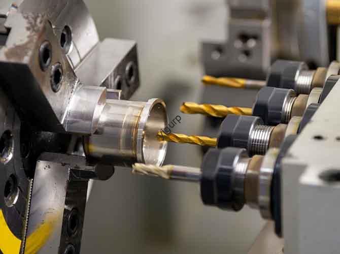
- Endmill: The rotating cutting tool. Unlike drill bits (which have a pointed tip for axial cutting), endmills have cutting edges on the sides and often the tip—allowing them to cut in multiple directions.
- Workholding Device: Clamps or vises that secure the workpiece. Poor workholding causes vibration, which ruins precision; industrial setups often use vacuum chucks or custom jigs for stability.
- Control System: For manual mills, this is a hand crank; for CNC mills, it’s a computer program (Code G) that automates tool movement. CNC controls allow for repeatability—producing 100 identical parts as easily as one.
The Milling Process in 5 Étapes simples
While CNC milling adds automation, the basic workflow stays consistent:
- Prepare the Workpiece: Cut the raw material (métal, plastique, bois) to a rough size (leaving 1–5mm of material for milling) and clean it to remove oil or debris.
- Secure the Workpiece: Clamp it to the mill’s table using a vise or chuck. Pour les pièces délicates (comme du plastique), use soft jaws to avoid damage.
- Set Up the Endmill: Install the correct endmill (par ex., a flat-end mill for slots, a ball-end mill for curved surfaces) and align it with the workpiece’s starting point (called “zeroing”).
- Program or Adjust Settings: For CNC, load a G-code program that defines tool path, vitesse, et vitesse d'avance. For manual mills, set the spindle speed (RPM) and hand-crank the table to move the workpiece.
- Start Milling: Turn on the spindle, start the tool rotation, and begin removing material. Pause periodically to check for tool wear or workpiece damage.
Real-World Example: A small automotive parts shop uses a CNC mill to make aluminum brackets. Their process: they cut 6061 aluminum into 100x100mm blocks, secure them with a vacuum chuck, use a 10mm flat-end mill, and run a 15-minute G-code program. Le résultat: 50 identical brackets per hour with a tolerance of ±0.002 inches—far more precise than manual methods.
Types of Milling Manufacturing Processes
Not all milling is the same—different techniques are used based on the part’s shape, matériel, et besoins de précision. Below are the most common types, with use cases and key differences:
1. Face Milling vs. Peripheral Milling
These are the two primary categories, distinguished by how the endmill interacts with the workpiece:
| Taper | Comment ça marche | Idéal pour | Tool Used | Avantage clé |
|---|---|---|---|---|
| Fraisage du visage | The endmill’sface (top surface) cuts the workpiece’s top face, creating a flat, surface lisse. | Smoothing the top of a block (par ex., aluminum plates for electronics). | Face mill (has multiple cutting teeth on the face). | Fast material removal; achieves surface finishes as smooth as Ra 0.8 µm. |
| Peripheral Milling | The endmill’sside edges cut the workpiece, creating slots, rainures, or vertical features. | Making slots in a gear or channels in a plastic housing. | Flat-end mill or ball-end mill. | Creates complex 2D shapes; ideal for deep cuts (up to 5x the endmill diameter). |
Étude de cas: A medical device manufacturer uses face milling to smooth the surface of titanium implant bases (requiring Ra 0.4 μm finish) and peripheral milling to cut 2mm-wide slots for screws. By combining both techniques, they meet the strict FDA standards for implant precision.
2. CNC Milling vs. Manual Milling
The choice between automated and manual milling depends on production volume and complexity:
- Manual Milling: Controlled by hand cranks—no computer required. Best for small batches (1–10 pièces) or simple shapes (par ex., a single wooden bracket). Avantages: Faible coût (entry-level machines under $2,000); easy to learn. Inconvénients: Lent (1–2 parts per hour); moins précis (tolerances of ±0.01 inches); prone to human error.
- Fraisage CNC: Automated via G-code. Best for large batches (100+ parties) or complex 3D shapes (par ex., a smartphone’s metal frame). Avantages: Rapide (20–100 parts per hour); highly precise (±0,0005 pouces); répétable. Inconvénients: High upfront cost; requires G-code knowledge.
Key Data: According to theManufacturing Technology Insights 2024 report, 78% of manufacturers now use CNC milling for production—up from 55% in 2019—due to its ability to reduce labor costs by 40% and material waste by 25%.
3. 2D contre. 3Fraisage D
These refer to the complexity of the part’s geometry:
- 2Fraisage D: The tool moves only in two axes (X and Y), cutting flat features like slots or holes. Used for simple parts (par ex., a plastic spacer with two holes).
- 3Fraisage D: The tool moves in three axes (X, Oui, Z), creating curved or contoured surfaces. Used for complex parts (par ex., a turbine blade or a guitar neck).
Pro Tip: For 3D milling, use a ball-end mill—the rounded tip creates smooth curves without sharp edges. A flat-end mill would leave “stepped” marks on curved surfaces.
Critical Factors for Successful Milling
Even with the right equipment, milling can fail if you ignore key variables. Below are the four most important factors to master, with actionable tips:
1. Choosing the Right Endmill
The endmill is the “engine” of milling—pick the wrong one, and you’ll get poor cuts or broken tools. Consider three factors:
- Compatibilité des matériaux: Utiliser de l'acier rapide (HSS) endmills for wood or plastic (faible coût, easy to sharpen). For metal (aluminium, acier, titane), use carbide endmills—they’re harder and resist heat better. For super-hard materials (alliage de titane), use cobalt carbide (adds 10–15% more wear resistance).
- Number of Flutes: Flutes are the grooves on the endmill that remove chips. Use 2-flute endmills for wood/plastic (they clear chips faster, preventing clogging). Use 4–6 flute endmills for metal (more flutes mean smoother cuts, but they need slower feed rates to avoid overheating).
- Revêtement: Coatings reduce friction and extend tool life. For aluminum, use an aluminum titanium nitride (AlTiN) coating—it resists heat up to 600°C. Pour l'acier, use a titanium carbonitride (TiCN) coating—it’s harder and works well at lower speeds.
Exemple: A machinist tried using a 2-flute HSS endmill for stainless steel—after 5 minutes, the tool overheated and lost its sharpness. Switching to a 4-flute carbide endmill with TiCN coating let them mill 50 parts before needing a tool change.
2. Vitesse de broche (RPM) and Feed Rate
Vitesse (how fast the endmill spins) et vitesse d'avance (how fast the workpiece moves) determine cut quality and tool life. Using the wrong values causes:
- Too High Speed: Overheats the endmill, leading to tool wear or melting (for plastic).
- Too Low Speed: Leaves rough surfaces and increases cutting time.
- Too High Feed Rate: Breaks the endmill (especially for brittle materials like ceramic).
- Too Low Feed Rate: Causes “rubbing” (the endmill doesn’t cut, just scrapes the material), leading to heat buildup.
Formula for Spindle Speed: RPM = (Cutting Speed × 12) / (π × Endmill Diameter). Cutting speeds vary by material:
- Aluminium: 300–500 SFM (surface feet per minute)
- Acier: 100–200 SFM
- Titane: 50–100 SFM
Exemple: For a 0.5-inch carbide endmill cutting aluminum (400 SFM): RPM = (400 × 12) / (3.14 × 0.5) ≈ 3,057 RPM.
3. Workholding
Poor workholding is the #1 cause of milling errors. Follow these rules:
- Secure Tightly: The workpiece should not move at all—even 0.001 inches of movement ruins precision. Use a vise with serrated jaws for metal, or a vacuum chuck for flat parts (like plastic sheets).
- Distribute Pressure Evenly: Pour les grandes pièces, use multiple clamps—too much pressure in one spot can warp the workpiece (especially for thin metals like 0.5mm aluminum).
- Avoid Blocking the Tool Path: Make sure clamps don’t get in the way of the endmill—this is a common mistake for beginners, leading to broken tools.
4. Coolant and Lubrication
Coolant reduces heat and friction, extending tool life and improving surface finish. The type depends on the material:
- Metal Milling: Use water-soluble coolant (for aluminum/steel) or oil-based coolant (pour le titane). Coolant can increase tool life by 50–100%, par le Journal of Materials Processing Technology.
- Wood/Plastic Milling: Use compressed air to blow away chips—coolant can warp wood or melt plastic.
Exemple de cas: A furniture maker switched from dry milling to air cooling for oak wood parts. They reduced chip buildup by 80% and eliminated “burn marks” on the wood surface, improving product quality.
Common Milling Problems and How to Fix Them
Even experts run into issues—here are the top 5 problems, their causes, and step-by-step solutions:
- Rough Surface Finish
- Causes: Dull endmill, too high feed rate, or vibration from loose workholding.
- Fix: Replace the endmill; reduce feed rate by 20%; re-tighten the workpiece or use a stiffer vise.
- Endmill Breakage
- Causes: Too high feed rate, too low spindle speed, or tool collision with clamps.
- Fix: Lower feed rate by 30%; increase RPM to the recommended value; check tool path for clamp interference before starting.
- Workpiece Warping
- Causes: Too much clamping pressure (for thin materials) or heat buildup (for plastic/soft metals).
- Fix: Use soft jaws or reduce clamp pressure; switch to a coolant system to lower temperature.
- Inaccurate Dimensions
- Causes: Incorrect zeroing (tool not aligned with workpiece), worn endmill, or machine calibration issues.
- Fix: Re-zero the tool using a touch probe; replace the endmill; calibrate the mill’s axes (follow the manufacturer’s guide).
- Chip Clogging
- Causes: 2-flute endmill (for metal), low spindle speed, or insufficient coolant/air.
- Fix: Switch to a 4-flute endmill; increase RPM; use compressed air or coolant to clear chips.
Yigu Technology’s Perspective on Milling Manufacturing
Chez Yigu Technologie, we’ve supported hundreds of manufacturers in optimizing their milling processes—from small workshops to large aerospace suppliers. Our biggest takeaway: milling success isn’t just about buying expensive CNC machines—it’s about matching the right tools, paramètres, and workflows to your specific part. Par exemple, a client making plastic medical trays was struggling with warping; we recommended switching from a 2-flute HSS endmill to a 4-flute carbide endmill with air cooling, which reduced warping by 90%. We also see a growing trend toward “hybrid milling” (combining CNC with additive manufacturing) for complex parts—milling shapes that 3D printing can’t achieve, while using 3D printing for custom jigs that improve workholding. For beginners, we advise starting small: invest in a mid-range benchtop CNC mill ($3,000–$10,000) and practice with aluminum (it’s forgiving and affordable) before moving to harder materials. Enfin, prioritize preventive maintenance—cleaning the mill’s table and lubricating axes weekly can extend machine life by 3–5 years.
FAQ: Common Milling Manufacturing Questions
1. What materials can be milled?
Nearly any solid material: métaux (aluminium, acier, titane, laiton), plastiques (ABS, PVC, polycarbonate), bois (chêne, érable, plywood), composites (fibre de carbone, fibre de verre), and even ceramics (with specialized carbide endmills).
2. How much does a milling machine cost?
Costs vary widely:
- Benchtop manual mill: $500–$2,000 (for hobbies).
- Benchtop CNC mill: $3,000–$15,000 (pour les petits lots).
- Industrial CNC mill: $50,000–$500,000+ (pour la production de masse).
3. Do I need to know G-code for CNC milling?
For basic projects, no—many CNC mills come with software (par ex., Fusion 360, VCarve) that lets you design parts and generate G-code automatically. Pour pièces complexes, learning basic G-code (par ex., G00 for rapid movement, G01 for linear cutting) helps troubleshoot issues.
4. What’s the difference between a mill and a router?
Routers are smaller, use high speeds (10,000–30 000 tr/min), and are best for soft materials (bois, plastique). Mills are larger, use lower speeds (1,000–10 000 tr/min), and can cut hard materials (métal, composites) with higher precision.
5. How long does it take to learn milling?
Manual milling: 1–2 weeks to master basic cuts (machines à sous, trous). Fraisage CNC: 1–2 months to learn design software and generate G-code for simple parts. Advanced skills (3Fraisage D, hard material cutting) take 6+ months of practice.