Making hardware prototypes is the process of creating physical, modèles à base de métal pour vérifier la conception d’un produit, structure, et faisabilité fonctionnelle – essentielle pour détecter les défauts avant la production en série. Contrairement à l’impression 3D plastique/résine (qui privilégie la vitesse), hardware prototyping focuses on propriétés des matériaux (force, résistance à la température) et precision processing (Usinage CNC, estampillage). Cet article détaille son flux de travail étape par étape, material/process choices, contrôles de qualité, and real-world applications to guide teams through successful prototype creation.
1. What Are the Core Goals of Making Hardware Prototypes?
Avant de commencer, clarify your objectives—they will shape every decision from material selection to processing methods.
| But | Description | Real-World Use Case |
| Functional Verification | Test if the prototype works as intended (par ex., load-bearing, ajustement de l'assemblage). | A CNC-machined aluminum bracket for a drone—check if it supports the drone’s weight without bending. |
| Appearance Confirmation | Ensure the prototype matches design aesthetics (couleur, état de surface). | A stainless steel smartphone frame—verify if the anodized matte finish aligns with brand guidelines. |
| Assembly Testing | Validate how the prototype fits with other components (par ex., vis, connecteurs). | A copper electronic connector—test if it plugs into a circuit board securely. |
| Material Validation | Confirm the chosen metal performs in real-world conditions (par ex., résistance à la corrosion). | UN 316 stainless steel marine sensor housing—check if it resists saltwater damage. |
2. What Is the Step-by-Step Workflow for Making Hardware Prototypes?
The process follows a linear, detail-driven sequence—skipping any step risks costly reworks.
2.1 Design Stage: Lay the Foundation
- Demand Analysis: Define key requirements:
- Material needs (par ex., aluminum alloy for lightweight, acier inoxydable pour la résistance à la corrosion).
- Précision dimensionnelle (±0.05mm for precision parts like gears; ±0.1mm for general parts like brackets).
- Traitement de surface (placage, spraying, anodisation) et post-traitement (trous filetés, rainures).
- 3Modélisation D & Dessin: Use CAD software (SolidWorks, UG NX, AutoCAD) créer:
- A 3D model of the prototype.
- 2D engineering drawings marked with tolérances (par ex., ±0,05 mm) et rugosité de la surface (Ra 1.6~3.2 for normal processing; Râ 0.8 for high gloss).
2.2 Matériel & Process Selection: Match to Your Goals
Choose materials and processes based on your prototype’s purpose, complexité, et le volume.
2.2.1 Material Selection Guide
| Matériel | Propriétés clés | Applications idéales |
| Alliage d'aluminium (6061, 6063) | Léger, facile à usiner, faible coût. | Shells, pièces structurelles (cadres de drones, boîtiers d'ordinateurs portables). |
| Acier inoxydable (304, 316) | Résistant à la corrosion, fort. | Pièces de précision, équipement extérieur (marine sensors, medical tool handles). |
| Copper/Brass | Excellente conductivité, heat dissipation. | Connecteurs électroniques, dissipateurs de chaleur (phone charging ports, CPU coolers). |
| Carbon Steel/Alloy Steel | Haute résistance, résistant à l'usure. | Load-bearing mechanical parts (engrenages, bagues, supports automobiles). |
2.2.2 Processing Method Selection
| Method | Idéal pour | Exemple |
| Usinage CNC | Haute précision, formes complexes (courbes, fils de discussion, rainures). | UN 6061 aluminum drone propeller hub with intricate threading. |
| Stamping/Sheet Metal | Thin-walled parts (≤3mm thick) like shells or brackets. | UN 304 stainless steel laptop chassis (cut via laser, bent into shape). |
| Impression 3D en métal (GDT) | Complex structures unachievable with CNC/stamping. | A titanium medical implant with internal lattice structures. |
| Welding/Assembly | Combining multiple components (par ex., charnières, snap structures). | Welding two aluminum brackets to form a car seat frame. |
2.3 Production: Build the Prototype
Below are the most common production processes (CNC machining and stamping) with key steps:
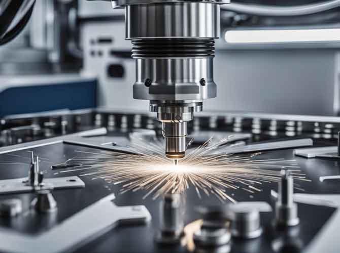
2.3.1 Usinage CNC (for Precision Parts)
- Programmation & Toolpath Planning: Generate G-code from the 3D model; set cutting parameters (rotational speed, vitesse d'avance, depth of cut). Choose tools (flat cutter for flat surfaces, ball cutter for curves) — carbide inserts work best for steel.
- Clamping & Tool Setting: Fix the metal billet to the CNC table; use a dial indicator to ensure perpendicularity. Calibrate the tool’s starting position with a tool setter to avoid deviations.
- Roughing & Finition:
- Roughing: Remove excess material quickly (large diameter tools, high feed rate); leave 0.5~1mm allowance.
- Finition: Refine the surface (small diameter tools, low feed rate) to meet design tolerances/roughness.
- Ébavurage & Cleaning: Use files/sandpaper to remove burrs; clean with an ultrasonic cleaner to eliminate oil/debris.
2.3.2 Stamping/Sheet Metal (for Thin-Walled Parts)
- Conception de moules & Plate Cutting: Design blanking/bending/stretching molds; cut the sheet metal (1~3mm thick) with a laser cutter or wire EDM.
- Stamping Molding: Use a punch to shape the metal (suppression, flexion, stretching); add secondary molding/hot pressing for complex surfaces.
- Soudage & Assemblée: Weld (argon arc, laser) or rivet parts together; sand welds and check for waterproof/airtight tightness if needed.
2.4 Traitement de surface: Enhance Function & Esthétique
Surface treatments protect the prototype and match final product looks:
| Traitement | Processus | Avantages |
| Pulvérisation | Sandblasting → Primer → Drying → Top Coat → Baking | Couleurs personnalisées (piano black, matte gray); résistance aux rayures. |
| Galvanoplastie | Chemical Degreasing → Pickling → Nickel/Chrome Plating → Polishing | Shiny finish; résistance à la corrosion (ideal for stainless steel/copper). |
| Anodisation (Aluminium) | Electrolytic oxidation to create a dense oxide film | Color options (noir, argent); improved wear/corrosion resistance. |
| Silk Screen/Laser Engraving | Silk screen: Print text/logos with epoxy ink; Laser: Engrave serial numbers/QR codes | Traçabilité; brand identification. |
2.5 Contrôle qualité: Ensure It Meets Standards
Skip inspection, and you risk missing flaws that derail production. Use these tests:
- Contrôle dimensionnel: Use a coordinate measuring machine (MMT) or micrometer to check key dimensions against design tolerances.
- Functional Tests: Simulate real use — test assembly fit, moving part fluency (charnières, diapositives), and load-bearing capacity.
- Inspection visuelle: Check for scratches, dents, or color aberrations; use a gloss meter to verify finish (highlight, mat).
3. What Are Common Problems & Solutions?
Even with careful planning, issues arise. Here’s how to fix them:
| Problème | Root Cause | Solution |
| Machining Deformation | Uneven material allowance or stress release during cutting. | Optimize tool paths for uniform allowance; pre-treat blanks with annealing (heat treatment to reduce stress). |
| Poor Surface Roughness | Worn tools or incorrect cutting parameters. | Replace tools every 50~100 parts; adjust rotational speed (increase for smoother surfaces) et vitesse d'avance (decrease for precision). |
| Welding Defects (porosité, non-fusion) | Improper welding parameters or unstable weldment positioning. | Optimize current/voltage; secure parts with a fixture during welding. |
4. What Are the Advantages & Limites?
Weigh these to decide if hardware prototyping fits your project:
Avantages
- Material Realism: Propriétés (force, conductivité) match mass-produced metal parts — no surprises later.
- Haute précision: Achieves tight tolerances (±0,05 mm) for complex parts like gears or medical components.
- Polyvalence esthétique: Multiple surface treatments (anodisation, placage) simulate final product looks.
Limites
- Coût élevé: CNC machining or stamping molds can cost \(1,000~\)5,000 — more than 3D printing.
- Longer Cycles: Takes 1~2 weeks (contre. 3~7 days for plastic 3D printing), especially for complex parts.
- Small-Batch Inefficiency: Per-unit cost drops with mass production, but stays high for 1~10 prototypes.
5. What Are Real-World Application Scenarios?
Hardware prototyping is used across industries to solve specific challenges:
- Mechanical Equipment: Test precision parts like gears (for fit) or bushings (pour la résistance à l'usure).
- Electronique grand public: Validate aluminum alloy heat sinks (pour la dissipation de la chaleur) or stainless steel phone brackets (pour la durabilité).
- Dispositifs médicaux: Check ergonomics of surgical instrument handles (acier inoxydable) or compatibility of implant components (titane).
- Automobile: Verify assembly of lightweight aluminum interior parts or corrosion resistance of stainless steel exterior trims.
Yigu Technology’s Perspective
Chez Yigu Technologie, we see making hardware prototypes as a “design insurance policy.” Too many clients rush to mold opening without validating metal prototypes—only to discover their aluminum bracket bends under load or their stainless steel part corrodes. Our approach: We work with teams to select the right material (par ex., 6061 aluminum for drones, 316 stainless steel for marine parts) and optimize CNC parameters to cut lead times by 30%. Par exemple, we helped an automotive client fix a welding defect in their bracket prototype in 3 jours, avoiding a $10k mold rework. Investing in hardware prototypes isn’t expensive—it’s cheaper than fixing mass production failures.
FAQ
- Can we use 3D printing (plastique) instead of hardware prototyping for metal parts?
No—plastic prototypes can’t replicate metal’s strength or conductivity. Par exemple, a plastic drone bracket may seem to fit, but a metal one could bend under real flight loads. Hardware prototyping ensures material performance matches your needs.
- How long does making a hardware prototype take?
It depends on complexity: A simple CNC-machined aluminum bracket takes 5~7 days; a complex stamped stainless steel part with anodizing takes 10~14 days. This is longer than plastic 3D printing but critical for accuracy.
- What’s the most cost-effective material for hardware prototypes?
Alliage d'aluminium (6061/6063) is the cheapest and easiest to machine—ideal for functional tests or non-corrosive environments. Acier inoxydable (304) costs more but is worth it for outdoor or medical applications needing corrosion resistance.