Les défauts de moulage sous pression (des imperfections de surface aux fissures internes) coûtent aux fabricants en moyenne 5 à 12 % de la valeur de production annuelle. (données de l'industrie). Ces défauts obligent non seulement à des reprises ou à la mise au rebut, mais compromettent également les performances des pièces., spécialement pour les composants critiques pour la sécurité comme les capteurs automobiles ou les supports aérospatiaux. Alors que des processus tels que le moulage sous pression en chambre chaude (pour alliages à bas point de fusion) or cold chamber die casting (for high-melting metals) have unique defect risks, most issues stem from shared pain points: mold design flaws, parameter mismatches, or material inconsistencies. But what do these common defects look like? What causes them? And how can you fix or prevent them? This article answers these questions with detailed classifications, exemples concrets, and actionable solutions.
1. Classification of Common Die Casting Defects: 5 Core Categories
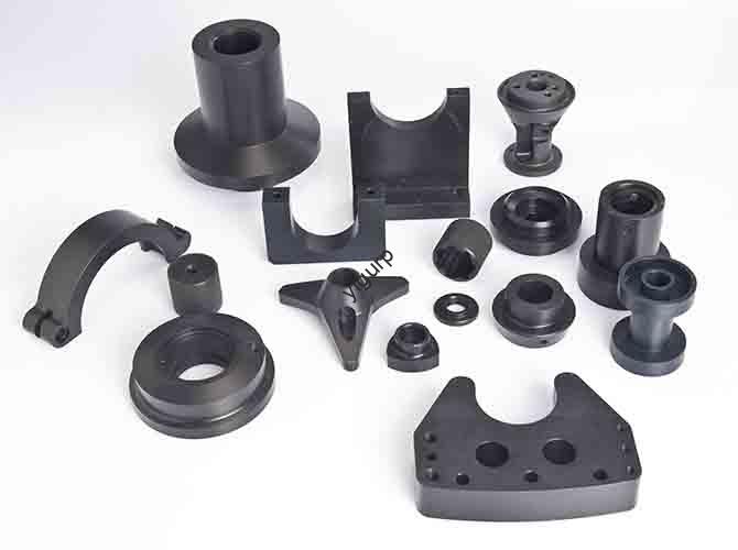
Die casting defects are grouped by their location (surface vs. interne) and root cause. The table below breaks down 5 key categories, with defect characteristics, high-incidence areas, and visual cues:
| Defect Category | Specific Defect | Key Characteristics | High-Incidence Areas | Detection Method |
| Filling Defects | Undercasting | Metal liquid fails to fill the cavity; incomplete part shape or cavities. | End of castings, narrow deep cavities (par ex., USB connector slots). | Inspection visuelle; mesure dimensionnelle (part shorter than design). |
| Cold Separation | Low-temperature metal flows dock but don’t fuse; irregular linear gaps (may penetrate); often with flow marks or surface bubbles. | Thick-thin wall transitions (par ex., boîtiers de capteurs automobiles). | Inspection visuelle; ultrasonic testing (UT) for hidden gaps. | |
| Flow Marks | First-entering metal forms a thin layer; covered by subsequent metal, leaving flow-direction traces; partial sunken feel. | Large flat surfaces (par ex., laptop hinge bases); near gates. | Inspection visuelle; touch test (detects slight depressions). | |
| Surface Damage Defects | Abrasion (Strain) | Surface scars from metal adhesion or insufficient mold draft; severe cases have cracks. | Mold release direction (par ex., cylindrical part edges). | Inspection visuelle; magnifying glass (10×) for fine scars. |
| Pockmarks | Small pockmark-like areas; rough surface texture. | Caused by low mold/alloy temperature during filling. | Inspection visuelle; surface roughness tester (Râ >6.3μm indicates defects). | |
| Mesh Burrs | Mesh-shaped bulges and metal burrs; caused by mold thermal fatigue. | Mold parting surfaces (par ex., zinc alloy faucet handles). | Inspection visuelle; edge feel (detects sharp burrs). | |
| Abnormal Shape Defects | Depression (Rétrécissement) | Concave areas on smooth surfaces; often with dimples. | Thick-walled areas or wall thickness transitions (par ex., battery terminal bases). | Inspection visuelle; numérisation laser (measures surface flatness). |
| Deformation (Warping) | Overall/partial geometry mismatch with design; par ex., bent brackets. | Thin-walled parts (par ex., Dissipateurs de chaleur LED); large flat components. | Dimensional testing (par ex., calipers for bending angle); MMT (Machine de mesure de coordonnées). | |
| Wrong Edge (Mismatch) | Relative displacement on both sides of the parting surface; step-like gaps. | Mold split lines (par ex., toy car bodies). | Inspection visuelle; feel test (detects step differences). | |
| Internal Quality Defects | Rétrécissement & Loosening | Holes or loose tissue from solidification contraction; faible densité. | Thick-walled cores (par ex., engine block ribs); wall thickness changes. | X-ray flaw detection; essai de densité (lower than material standard). |
| Bubbles | Gas accumulation under the epidermis; bulging bubbles (may penetrate or be closed); easy to crack when stressed. | Near mold vents (par ex., 3C part inner cavities). | X-ray testing; traitement thermique (bubbles expand and become visible). | |
| Cracks | Filamentous gaps; cold cracks (no oxidation, fragile) or hot cracks (oxidized edges, ductile). | High-stress areas (par ex., part corners); après traitement thermique. | UT testing; dye penetrant inspection (PPP) for surface cracks. | |
| Other Defects | Flash (Fluff) | Excess metal flakes on edges or splices; thin and brittle. | Mold parting surfaces, insert gaps (par ex., bathroom hardware joints). | Inspection visuelle; edge trimming (removes excess material). |
| Imprinting | Uneven marks from pusher/insert splicing; par ex., circular dents from ejector pins. | Pusher contact areas (par ex., part bottoms). | Inspection visuelle; touch test (detects unevenness). | |
| Colored Spots | Heterochromatic spots (par ex., noir, brun); caused by paint carbides or punch oil. | Surface of decorative parts (par ex., zinc alloy toy casings). | Inspection visuelle; solvent wiping (tests if spots are removable). | |
| Superposition (Clamping) | Obvious metal layers inside the part; thick flash on parting surfaces. | Caused by multiple metal flow layers not fusing. | Sectioning inspection; X-ray testing (shows layer boundaries). |
2. Root Causes: Why Defects Happen (3 Key Links)
Most die casting defects trace back to failures in conception de moule, paramètres de processus, or material quality. Below is a detailed breakdown of causes for high-frequency defects:
UN. Mold Design Flaws (30–40% of Defects)
Mold issues create inherent risks for filling, surface, and shape defects:
- Insufficient Draft Angle: Draft <1° (for zinc alloys) causes metal adhesion, leading to abrasion (strain) and deformation.
- Poor Gate/Exhaust Design: Small gate size (par ex., <1mm for thin parts) slows filling, causing undercasting; blocked exhaust grooves (profondeur <0.2mm) trap gas, conduisant à des bulles.
- Uneven Cooling Channels: Cooling channel spacing >20mm creates temperature gradients (>30°C), causing cold separation and shrinkage depressions.
- Thermal Fatigue: Mold used >100,000 shots without maintenance develops cracks, leading to mesh burrs and layering.
B. Process Parameter Mismatches (40–50% of Defects)
Incorrect settings during casting amplify defect risks—especially for filling and internal defects:
| Defect | Key Parameter Cause | Quantitative Thresholds (Alliages de zinc) |
| Undercasting | Low injection pressure/speed; low alloy temperature. | Pression <5MPa; vitesse <0.5MS; température <380°C. |
| Cold Separation | Slow filling speed; large temperature drop between metal and mold. | Vitesse <0.8MS; température du moule <150°C (alloy temp 400°C). |
| Bubbles | High injection speed (turbulence); insufficient holding pressure. | Vitesse >2MS; holding pressure <8MPa. |
| Shrinkage Depression | Short holding time; low holding pressure. | Holding time <5s; pression <10MPa. |
| Deformation | Uneven cooling time; mold opening too early. | Temps de refroidissement <3s (pièces fines); mold opening <2s after solidification. |
C. Material Quality Issues (10–20% of Defects)
Impure or unstable materials introduce internal and surface defects:
- Alloy Impurities: Iron content >1.2% (alliages de zinc) causes hard particles, leading to pockmarks and cracks.
- Moisture/Gas Content: Hydrogen content >0.3cc/100g (alliages d'aluminium) creates bubbles during solidification.
- Oxide Slag: Unfiltered molten metal (slag content >0.5%) causes layering and shrinkage loosening.
3. Solution Framework: Fix & Prevent Defects
Resolving die casting defects requires targeted fixes for root causes—follow this 3-step approach for long-term results:
UN. Targeted Fixes for High-Frequency Defects
For common defects, use these proven solutions tailored to cause and defect type:
| Defect | Immediate Fix | Long-Term Prevention |
| Undercasting | Increase injection pressure (by 2–5MPa) or speed (by 0.2–0.5m/s); raise alloy temperature (by 10–15°C). | Optimize gate size (match to part thickness: gate width = 2× part thickness); clean exhaust grooves weekly. |
| Cold Separation | Preheat mold to 180–200°C (alliages de zinc); increase alloy temperature (by 15–20°C); use a larger gate. | Add diversion ribs (angle ≤10°) to guide uniform flow; install mold temperature controllers (±5°C tolerance). |
| Bubbles | Reduce injection speed (by 0.3–0.5m/s); extend holding time (by 2–3s); add vacuum exhaust (vacuum degree ≥90kPa). | Use inert gas protection (argon/nitrogen) during melting; filter molten metal with 20-ppi ceramic foam filters. |
| Shrinkage Depression | Increase holding pressure (by 3–5MPa); extend holding time (by 3–5s); add local cooling channels (near thick walls). | Optimize part design (reduce wall thickness difference to ≤2:1); use risers for thick-walled areas. |
| Abrasion (Strain) | Polish mold cavity (Ra ≤1.6μm); increase draft angle to 1.5–2°; apply mold release agent (mince, uniform layer). | Use wear-resistant mold materials (par ex., H13 steel for hot chamber dies); coat cavity with TiN (nitrure de titane) for zinc alloys. |
B. Mold Optimization: Build Defect-Resistant Designs
- Draft Angle: Ensure minimum draft of 1° for zinc alloys, 2° for aluminum alloys (prevents abrasion).
- Exhaust System: Add exhaust grooves (depth 0.1–0.2mm, width 5–10mm) at final filling zones; pour pièces complexes, use vent pins (diameter 0.5–1mm).
- Cooling Channels: Space channels 15–20mm apart; align with thick-walled areas (par ex., 5mm from 10mm-thick walls) to reduce temperature gradients.
- Gate Design: Use fan gates for large flat parts (ensures uniform filling); use pinpoint gates (diameter 0.8–1.2mm) for small 3C components.
C. Contrôle des processus: Stabilize Parameters
- Contrôle de la température:
- Alloy temperature: 380–420°C (alliages de zinc), 680–720°C (alliages d'aluminium); use a digital thermostat (±5°C tolerance).
- Température du moule: 150–200°C (alliages de zinc), 200–250°C (alliages d'aluminium); monitor with infrared thermal imagers.
- Paramètres d'injection:
- Coulée sous pression en chambre chaude (zinc): Pressure 10–20MPa, speed 0.5–1.5m/s.
- Cold chamber die casting (aluminium): Pressure 30–80MPa, speed 2–5m/s.
- Contrôles de qualité:
- First-part inspection: Vérifier les dimensions, surface, and internal quality (X-ray for critical parts) at the start of each shift.
- Contrôle statistique des processus (CPS): Track parameters (température, pression) and defect rates; set control limits (par ex., ±10% for pressure).
4. Yigu Technology’s Perspective on Common Die Casting Defects
Chez Yigu Technologie, we view defects not as failures, but as opportunities to optimize processes. For hot chamber die casting clients (zinc alloy 3C parts), our AI-driven parameter control system—combining real-time temperature monitoring and adaptive pressure adjustment—reduced filling defects (undercasting, cold separation) depuis 8% à <1.5%. For cold chamber clients (aluminum automotive parts), our vacuum-assisted exhaust and ceramic foam filtration cut bubble and shrinkage rates by 60%.
We’re advancing two key solutions: 1) Digital twin simulation (MAGMA software) to predict filling defects before mold production; 2) Wear-resistant mold coatings (TiAlN) that extend mold life by 50%, reducing mesh burrs. Our goal is to help manufacturers shift from “defect repair” to “defect prevention”—cutting scrap rates to <2% and boosting production efficiency by 15%.
FAQ
- Can surface defects like flow marks or pockmarks be repaired after casting?
Yes—minor flow marks can be removed by mechanical polishing (800–1200-grit sandpaper) or chemical etching (for aluminum alloys). Pockmarks may require putty filling (pour les pièces non critiques), but severe cases need scrapping. We recommend fixing root causes (par ex., adjusting injection speed) instead of relying on post-repair.
- Why do internal defects like bubbles or shrinkage often go undetected until later?
Internal defects are hidden under the surface—they may only appear after heat treatment (bubbles expand) or stress testing (cracks form). To detect them early, use X-ray flaw detection for critical parts (par ex., capteurs automobiles) and density testing (ensure ≥99.5% density for aluminum alloys).
- Do common defects differ between hot chamber and cold chamber die casting?
Yes—hot chamber (zinc) is prone to surface defects (abrasion, marques) due to mold adhesion and low pressure; cold chamber (aluminium) faces more internal defects (bulles, rétrécissement) due to high-temperature metal and turbulent filling. Our solutions are tailored: for hot chamber, we optimize draft and mold release; for cold chamber, we focus on vacuum and filtration.