FDM Basics
Fused Deposition Modeling is a key part of modern additive manufacturing. Cela fonctionne en plaçant le matériau fondu dans un chemin planifié, couche par couche, construire un objet réel à partir d'un fichier informatique. Cette technologie n'est pas réservée aux amateurs; ça change l'ingénierie, conception de produits, and manufacturing by making things faster and more flexible than ever before.
Important Terms
To understand Fused Deposition Modeling, it’s important to know where it fits in the industry. Think of these terms like this: “Vehicle” is the big category, “Car” is a specific type, et “Sedan” is a particular model.
- Fabrication additive (SUIS): This is the industry term for the overall process of building objects layer by layer from computer data. C'est le “Vehicle.”
- 3D Impression: This is the more common term that most people know for additive manufacturing, often used by consumers and small businesses. C'est le “Car.”
- Modélisation des dépôts fondus (FDM): This is a specific, trademarked type of additive manufacturing process that uses plastic filament. C'est le “Sedan.” The general term is Fused Filament Fabrication (FFF).
Comment ça marche
The process is simple in idea. A long strand of solid plastic material, called filament, is fed from a spool into a heated part of the printer called an extruder. The extruder melts the filament and pushes it through a small opening called a nozzle. The printer’s movement system, usually working on X, Oui, and Z directions, moves the extruder head to trace a cross-section of the object, placing a thin line of melted plastic. This layer cools and hardens almost right away, sticking to the layer below it. This process repeats, couche par couche, until the whole object is finished.
Impact on Manufacturing
The importance of Fused Deposition Modeling lies in how versatile and easy to use it is. It has completely changed how many industries work by providing powerful abilities:
- Prototypage rapide: Greatly reduces the time between initial design and a physical model, letting engineers and designers test shape, ajuster, and function in hours instead of weeks.
- Custom Tools and Fixtures: Allows the on-demand creation of manufacturing aids that improve the efficiency and accuracy of traditional processes like assembly and machining.
- Production en petits lots: Makes it affordable to produce end-use parts without the huge upfront cost and wait time associated with injection molding or other mass-production methods.
- Making Manufacturing Available to Everyone: Its low cost has brought powerful manufacturing abilities to small businesses, laboratoires de recherche, schools, and even individuals.
FDM technology consistently makes up the largest share of the additive manufacturing market in terms of units sold. According to market studies, such as those from Grand View Research, the FDM sector is expected to continue growing strongly, driven by improvements in materials and hardware that expand its use from prototyping to making functional parts.
The FDM Process
Understanding the workflow from a digital idea to a real object is essential for anyone looking to use this technology. The process can be broken down into five clear steps.
Étape 1: Digital Blueprint
Everything begins with a digital model. This is typically created using Computer-Aided Design (GOUJAT) logiciel. Once the 3D model is complete, it is saved, usually as an STL or OBJ file. This file format describes the surface shape of the object as a mesh of triangles.
This mesh file is then imported into a special program called a “slicer.” Slicer software, such as Cura or PrusaSlicer, is the critical link between the 3D model and the printer. Il “slices” the model into hundreds or thousands of horizontal layers and creates the specific machine instructions, known as G-code, that will guide the printer’s every move. Within the slicer, the operator sets all the important print settings: hauteur de couche, infill density and pattern, vitesse d'impression, and temperatures for the nozzle and build plate.
Étape 2: Machine Preparation
Before the print can begin, the machine must be prepared. This involves making sure the build plate—the surface on which the part is printed—is clean and level. For materials that tend to warp, an adhesive like a glue stick or a special coating may be applied to help the first layer stick. A spool of the chosen filament material is mounted on the printer, and the end of the filament is fed into the extruder mechanism until it reaches the heated nozzle.
Étape 3: Heating and Placing Material
With the G-code loaded and the machine prepared, the printing process begins. Le “hot end,” which is the heating block and nozzle assembly, heats the filament to its specific melting point, which can range from around 200°C for PLA to over 400°C for high-performance plastics.
The movement system, made up of motors, ceintures, and lead screws, precisely controls the movement of the extruder in the X and Y directions to trace the first layer. Once complete, the build plate or the movement system moves a tiny amount in the Z direction (equal to the layer height), and the process repeats for the next layer. The printer carefully places material, couche par couche, building the object from the ground up.
Étape 4: Cooling and Hardening
As the melted plastic is pushed out from the nozzle, it begins to cool and harden, sticking to the layer below it. This sticking is what gives the final part its strength. The rate of cooling is a critical process variable. Most FDM printers have a dedicated part cooling fan that directs airflow at the newly placed layer. This helps the material harden quickly, allowing for sharper details, better overhangs, and faster print speeds. Cependant, too much cooling can weaken the bond between layers, so finding the right balance is key.
Étape 5: Finition
Once the final layer is placed, the printer finishes its cycle, and the part is allowed to cool completely. The finished object is then removed from the build plate, sometimes requiring a scraper or spatula.
If the model had complex overhangs or hollow sections, it was likely printed with support structures. These temporary scaffolding elements must be removed. Breakaway supports are snapped off by hand or with tools. Soluble supports, printed with a different material, are dissolved in a specific solvent, leaving a clean surface behind. Selon l'application, further finishing steps can be performed, such as sanding to smooth layer lines, lissage à la vapeur (for materials like ABS) to achieve a glossy finish, ou peinture.
FDM Materials Guide
The material is the “fuel” of the FDM process, and the huge selection of available plastics is one of the technology’s greatest strengths. Choosing the correct material is critical, as it determines the cost, force, résistance à la température, and overall performance of the final part.
Standard Plastics
These are the affordable, easy-to-use workhorses of FDM, suitable for a wide range of applications from prototyping to hobby projects.
- PLA (Acide polylactique): The most popular FDM material. It is easy to print, requires no heated bed, has minimal warping, and comes in a huge variety of colors. It is also biodegradable under industrial composting conditions.
- ABS (Acrylonitrile Butadiène Styrène): Stronger, plus durable, and more temperature-resistant than PLA. It is the same plastic used in LEGO bricks. It requires a heated bed and an enclosed print chamber to prevent warping and cracking.
- PETG (Polyéthylène téréphtalate glycol): Offers a great balance of properties. It is nearly as easy to print as PLA but offers superior strength, durabilité, et résistance à la température, approaching the performance of ABS. It is also known for its excellent chemical resistance and food-safe grades.
High-Performance Plastics
These engineering-grade materials are used for demanding applications where mechanical strength, résistance chimique, and high-temperature performance are required. They often need specialized, high-temperature printers.
- Nylon (Pennsylvanie): Known for its exceptional toughness, durabilité, and low-friction properties. It is ideal for printing functional parts like gears, living hinges, and other components subject to wear.
- Polycarbonate (PC): One of the strongest materials available for desktop FDM. It has incredible impact strength and high-temperature resistance, making it suitable for functional prototypes and end-use parts that must withstand harsh environments.
- COUP D'OEIL & saindoux: Part of the PAEK family of ultra-performance polymers. These materials offer metal-like strength, extreme temperature and chemical resistance, and are naturally flame retardant. They are used in the most demanding aerospace, automobile, et applications médicales.
Flexible and Composite Filaments
These materials extend the capabilities of FDM beyond rigid plastics, enabling the creation of parts with unique properties.
- TPU/TPE: These are thermoplastic elastomers that behave like rubber. They are used to create flexible, impact-absorbing parts such as seals, joints, coques de téléphone, and wearable prototypes.
- Composite Filaments: These are base plastics (like PLA, PETG, or Nylon) that have been mixed with short strands of other materials to improve their properties. Carbon fiber-filled filaments offer significantly increased stiffness and strength, while glass-filled filaments improve thermal and dimensional stability. Other composites, like wood-filled or metal-filled filaments, are used primarily for looks.
| Matériel | Propriétés clés | Applications courantes | Print Requirements |
| PLA | Facile à imprimer, rigide, good detail, biodégradable | Visual prototypes, modèles conceptuels, non-functional parts | Low temp nozzle (190-220°C), no heated bed needed |
| ABS | Fort, durable, high temp resistance | Pièces fonctionnelles, protective housings, automotive prototypes | High temp nozzle (230-260°C), lit chauffant (100-110°C), enclosure |
| PETG | Fort, durable, bonne résistance chimique, faible retrait | Mechanical parts, food-safe containers, protective components | Med-high temp nozzle (230-250°C), lit chauffant (70-80°C) |
| Nylon (Pennsylvanie) | Difficile, flexible, résistant à l'usure, faible friction | Engrenages, living hinges, outillage, composants durables | High temp nozzle (240-270°C), lit chauffant, moisture sensitive |
| PC | Very strong, high impact and temp resistance | Prototypes fonctionnels, équipement de protection, drone parts | Very high temp nozzle (260-310°C), lit chauffant (>110°C), enclosure |
| TPU | Very flexible, semblable à du caoutchouc, impact absorbent | Scellés, joints, flexible prototypes, coques de téléphone | Specific print speeds, direct drive extruder recommended |
| Fibre de carbone | Very stiff, high strength-to-weight, dimensionally stable | Gabarits, luminaires, high-performance drone and RC parts | Abrasive; requires hardened steel nozzle |
Setting Optimization
Getting high-quality results with FDM is a science. Moving beyond default settings to fine-tune process settings is what separates a beginner from an expert. This section provides practical, experience-based advice on how to adjust key settings to solve common problems and achieve specific outcomes.
Vitesse, Temperature, and Quality
There is a basic trade-off in FDM between print speed, print quality, and part strength. You can typically optimize for two of these, but rarely all three at the same time.
- Vitesse d'impression (mm/s): Printing faster reduces job time but can lead to issues like ringing (ghosting artifacts on the surface) et, more critically, mauvaise adhérence des couches. A slower speed allows each layer to bond more effectively with the one below it, resulting in a stronger part.
- Température de la buse (°C): This is perhaps the most critical setting. Printing too hot can cause stringing, oozing, and loss of fine detail. Printing too cold is even worse; it leads to weak layer bonds (delamination) and can cause the extruder to jam as it struggles to push the under-melted filament. UN “temperature tower” calibration print is the best way to find the ideal temperature for any given filament spool.
Structural Strength
The strength of an FDM part is not just about the material; it’s about how the material is placed.
- Infill Density (%): This setting determines how much material is printed inside the part’s outer shell. A common misconception is that more infill always equals more strength. While a 100% infill part is solid, un 20-40% infill part is often sufficient. More important is the infill pattern. Patterns like Gyroid or Honeycomb provide excellent strength in multiple directions while using less material and time than a simple grid pattern.
- Wall/Shell Thickness: For most applications, the number of outer perimeters (walls or shells) has a far greater impact on part strength than infill density. Increasing the wall count from two to four can dramatically improve the part’s ability to withstand mechanical stress, often more effectively than increasing infill from 20% à 50%.
The Perfect First Layer
A successful print starts with a perfect first layer. Sur 90% of print failures can be traced back to first-layer issues like poor adhesion and warping.
- Bed Temperature: For materials like ABS, ASA, and Nylon, a heated bed is absolutely necessary. It keeps the base of the model warm throughout the print, reducing the thermal stress that causes the corners to lift off the bed—a problem known as warping.
- Z-Offset: This setting defines the exact distance between the nozzle tip and the build plate. It is the single most critical factor for adhesion. If the nozzle is too high, the extruded filament won’t stick. If it’s too low, it can clog the nozzle and damage the build surface. The goal is to achieve the perfect “squish,” where the filament is gently pressed onto the plate. We often start with a Z-offset of -0.05mm and fine-tune it live during the first layer until the lines are perfectly fused with no gaps.
- Adhesion Aids: When printing large parts or difficult materials, aids are essential. A brim is a single-layer extension around the base of the part that increases surface area and hold-down force. A raft is a disposable base printed underneath the entire part, providing a perfect surface for it to build upon. We found that for large ABS parts, a brim of 10-15 lines combined with an enclosure to maintain ambient temperature drastically reduced warping on our test prints.
Fine-Tuning Appearance
For models where looks are most important, two settings are key.
- Hauteur de couche (mm): This is the vertical resolution of the print. A smaller layer height (par ex., 0.1mm) creates a smoother surface with less visible layer lines but significantly increases print time. A larger layer height (par ex., 0.3mm) prints much faster but results in a rougher, more visibly layered part.
- Part Cooling Fan Speed (%): The cooling fan helps solidify material on sharp corners and overhangs, improving detail. Cependant, for materials like ABS, too much cooling can prevent layer adhesion and cause delamination. It’s often best to turn the fan off for the first few layers to maximize adhesion to the bed and then run it at a moderate speed (par ex., 40-60%) for the rest of the print.
FDM in Context
To truly understand the value of Fused Deposition Modeling, it’s helpful to compare it to other leading additive manufacturing technologies. Each process has distinct strengths and is best suited for different applications.
FDM vs. ANS
Stéréolithographie (ANS) was the first commercialized 3D printing technology. It works by using an ultraviolet (UV) laser to selectively cure a liquid photopolymer resin in a vat, couche par couche.
The key difference is resolution and surface finish. SLA can produce parts with incredibly fine details and a smooth, almost injection-molded quality surface that is impossible to achieve with FDM. Cependant, FDM has a significant advantage in material properties and cost. FDM uses robust, engineering-grade plastics that are often stronger and more durable than standard SLA resins. The machines and materials are also significantly more affordable and easier to handle, making FDM more accessible.
FDM vs. SLS
Frittage sélectif au laser (SLS) uses a high-powered laser to fuse together particles of a polymer powder. After one layer is sintered, a roller spreads a fresh layer of powder on top, and the process repeats.
The primary advantage of SLS is design freedom. Because the part is supported by the unfused powder surrounding it, SLS requires no dedicated support structures. This allows for the creation of incredibly complex geometries, pièces emboîtables, and internal channels that would be impossible to produce with FDM. SLS parts are also known for their excellent mechanical properties and consistency. The trade-off is cost and complexity. SLS machines are far more expensive and require a more involved workflow and facility setup than FDM printers.
Choosing the Right Process
| Feature | Modélisation des dépôts fondus (FDM) | Stéréolithographie (ANS) | Frittage sélectif au laser (SLS) |
| Core Technology | Extrusion of thermoplastic filament | Curing of photopolymer resin | Sintering of polymer powder |
| Coût | Faible (Machine & Matériel) | Moyen | Haut |
| Résolution | Low to Medium | Très élevé | Medium to High |
| Variété de matériaux | Très élevé (Plastiques, Composites, Flexibles) | Moyen (Resins with varied properties) | Moyen (Primarily Nylons) |
| Résistance de la pièce | Good to Excellent (Engineering-grade) | Fair to Good (Brittle unless using tough resins) | Excellent (Near isotropic) |
| Ideal Use Cases | Prototypes, jigs, luminaires, pièces fonctionnelles | High-detail models, visual prototypes, moules | Géométries complexes, pièces fonctionnelles, end-use production |
In summary, the choice depends on your primary goal:
- Pour low-cost rapid prototyping and strong functional parts, choose FDM.
- Pour high-detail models where looks and surface finish are critical, choose SLA.
- Pour complexe, durable parts with no support constraints, choose SLS.
Applications du monde réel
The true measure of a technology is its real-world impact. FDM is used across countless industries to solve real problems, speed up innovation, and create value.
FDM Across Industries
- Aérospatial: Used to create non-critical cabin components, environmental control system ducting, et, most importantly, custom jigs and fixtures for assembly and maintenance. High-performance materials like ULTEM and PEEK are certified for these applications.
- Automobile: Design studios use FDM to produce full-scale dashboard mockups and test the fit of new components. On the factory floor, FDM is used to print custom tools, assembly guides, and end-of-arm tooling for robots, reducing costs and lead times.
- Médical: Surgeons use FDM to print patient-specific anatomical models from CT and MRI scans to plan complex surgeries. It is also used for creating custom prosthetic prototypes and surgical guides that improve accuracy during procedures.
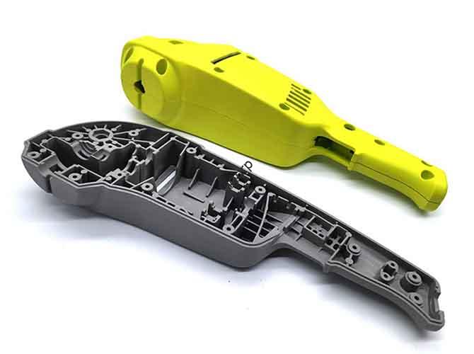
- Biens de consommation: Companies use FDM extensively to create functional prototypes for ergonomic testing and market feedback. This allows them to refine designs for products like power tools, appareils de cuisine, and electronic enclosures before committing to expensive injection mold tooling.
Étude de cas: A Custom Drone Mount
This example illustrates the power of FDM for agile product development.
- The Challenge: An engineering team needed a custom mount to attach a new sensor payload to an existing commercial drone. The mount had to be lightweight to preserve flight time, strong enough to withstand vibration and hard landings, and designed and produced within three days for a critical field test.
- Why FDM was Chosen: The choice was clear. FDM offered unmatched speed for iteration, zero tooling cost, and access to a range of materials with different properties. Machining the part would have been too slow and expensive for a one-off prototype.
- The Process in Action:
1. Itération 1 (PLA): The initial design was printed in PLA in just two hours. This quick, low-cost print was used purely to check the fit and mounting hole alignment. The test revealed a clearance issue with one of the drone’s arms.
2. Itération 2 (PETG): The CAD model was adjusted to fix the clearance issue. The part was then reprinted in PETG, a stronger material, to perform a functional test. The mount fit perfectly, but a static load test showed a potential weak point near a screw boss.
3. Final Design (Carbon Fiber-Nylon): The model was reinforced with a thicker wall and a fillet at the weak point. For the final version, the team used a carbon fiber-filled nylon filament. This composite material provided the high stiffness and low weight required for the flight-ready part.
- The Outcome: The team went from initial concept to a successful, field-tested functional prototype in under 48 heures. The total material cost was less than $20, a tiny fraction of what a machined alternative would have cost. FDM enabled a rapid, iterative design process that resulted in an optimized, on-demand solution.
The Future of FDM
Fused Deposition Modeling is a mature technology, but it is far from static. Continuous innovation in materials, matériel, and software is pushing the boundaries of what is possible and expanding its role in the manufacturing landscape.
Innovations in Materials
- Continuous Fiber Reinforcement: Systems are emerging that embed a continuous strand of carbon fiber, fibre de verre, or Kevlar within a plastic part as it is printed, creating components with a strength-to-weight ratio comparable to aluminum.
- Advanced Polymers: The development of new bio-compatible and bio-absorbable materials is opening doors for FDM in medical implants and tissue engineering.
Advancements in Hardware and Software
- Increased Speed: New motion systems, high-flow extruders, and advanced thermal management are enabling print speeds that are 5-10 times faster than current standards without sacrificing quality.
- AI-Powered Slicing: Future slicer software will use artificial intelligence to automatically analyze a model’s geometry and intended application to optimize hundreds of parameters, eliminating guesswork and ensuring a successful print on the first try.
- Accessibility of Advanced Features: Features once reserved for expensive industrial machines, such as multi-material printing, large build volumes, and heated chambers, are becoming standard on more affordable desktop systems.
FDM in Manufacturing 4.0
The most significant trend is FDM’s evolution from a prototyping tool to a legitimate production method. As the technology becomes faster, more reliable, and capable of producing stronger parts, its role in the digital factory grows. It is a key enabler of distributed manufacturing, where parts can be printed on-demand, close to the point of need, revolutionizing supply chains and inventory management.