El prototype metal stamping process is a specialized manufacturing method for creating small-batch (1–50 unidades) prototipos de metal dando forma a láminas de metal (0.5mm–3 mm de espesor) a través de troqueles y prensas. A diferencia del estampado de producción en masa (que usa caro, troqueles de gran volumen), prioriza la flexibilidad, rentabilidad, y rápida validación de la viabilidad del diseño, lo que lo hace fundamental para industrias como la electrónica, automotor, e ingenieria mecanica. Este artículo desglosa su flujo de trabajo paso a paso., material/tool choices, control de calidad, and key precautions to help teams avoid common pitfalls.
1. What Are the Core Goals of the Prototype Metal Stamping Process?
antes de empezar, clarify your objectives—they guide every decision from material selection to die design.
| Meta | Descripción | Ejemplo del mundo real |
| Design Validation | Verify if the prototype’s structure (agujeros, enfermedad de buzo, formas) aligns with 2D/3D drawings and functional needs. | Testing if a stainless steel electronic device shell (stamped with 4 agujeros de montaje) fits with internal circuit boards without interference. |
| Mass Production Feasibility Check | Identify potential issues (p.ej., material tearing, desviación dimensional) that could arise in large-scale stamping. | Simulating how an aluminum alloy automotive bracket bends during stamping—ensuring the process won’t cause cracks in mass production. |
| Assembly Compatibility Testing | Confirm the prototype fits with other components (plástica, electrónica, tornillos) in the final product. | Checking if a stamped copper connector (with M3 threads) securely fastens to a plastic sensor housing. |
| Costo & Cycle Time Estimation | Gather data (die costs, processing time) to forecast mass production budgets and timelines. | Using a prototype die’s \(500 cost and 2-hour stamping time to estimate that mass production dies will cost \)10,000 and produce 100 parts per hour. |
2. What Is the Step-by-Step Prototype Metal Stamping Workflow?
The process follows a linear, repeatable sequence—each stage builds on the previous one to ensure precision and consistency.
2.1 Paso 1: Preparación preliminar (Lay the Foundation)
This stage defines requirements and creates design documents to avoid rework later.
| Task | Key Details |
| Requirements Analysis | – Clarify prototype purpose: Visual verification, structural testing, or assembly matching.- Define material specs: Espesor (0.5mm–3mm), dureza (p.ej., 6061 aleación de aluminio: 95–110 HB), ductilidad (≥10% elongation for bending), and corrosion resistance needs.- Confirm quantity: 1–50 unidades (standard for prototype stamping). |
| Diseño & Drawing Creation | – Provide 2D CAD drawings or 3D STP/IGES models with: – Critical dimensions (p.ej., diámetro del agujero: 5mm ±0.1mm) y tolerancias (±0.1mm for most prototype parts). – Bending parameters: Bending radius (≥1x material thickness to avoid cracking) and angle (90° ±1°). – Special notes: Tratamiento superficial (enchapado, spraying), burr control (≤0,05 mm), or emulsion protection (to prevent rust during processing). |
2.2 Paso 2: Die Design & Producción (Choose the Right Tool)
Prototype dies prioritize cost and speed over high-volume durability. Select die type based on part complexity and batch size.
| Die Type | Mejor para | Rango de costos | Plazo de entrega | Ventajas clave |
| Simple Soft Dies (aleación de zinc, resina) | Basic parts (flat blanks, simple bends: p.ej., a rectangular aluminum bracket with 1 doblar). | \(300–\)1,000 | 2–5 días | Bajo costo, producción rápida; ideal for 1–10 units. |
| Multi-Process Soft Dies (Combined blanking + doblando) | Parts with 2–3 processes (p.ej., a stainless steel clip with 2 bends and 1 hole). | \(800–\)2,000 | 5–7 días | Handles moderate complexity without expensive hard tooling. |
| Semi-Hard Dies (Acero bajo en carbono) | Partes complejas (deep stretches, multiple holes: p.ej., a copper heat sink with 10 fins). | \(2,000–\)5,000 | 7–10 días | More durable than soft dies; suitable for 30–50 units. |
Critical Die Debugging Steps
- Gap Adjustment: Set die clearance to 5%–10% of material thickness (p.ej., 0.05mm–0.1mm for 1mm thick aluminum) to ensure clean cuts and prevent burrs.
- Force & Stroke Testing: Use a press to test punching force (p.ej., 5–10 tons for 1mm stainless steel) and stroke length—avoid overloading, which causes material tearing or die damage.
- Sample Trial: Stamp 1–2 test parts to check for dimensional accuracy; adjust die position or clearance if deviations exceed ±0.1mm.
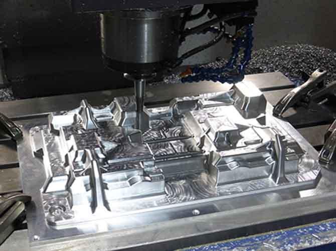
2.3 Paso 3: Stamping Processing (Shape the Metal)
Follow these sub-steps to transform metal sheets into prototypes, with strict quality checks at each stage.
- Material Cutting
- Cut metal sheets (p.ej., 6061 aluminio, 304 acero inoxidable) to size using laser cutting or shearing—reserve 1mm–2mm processing allowance for subsequent steps.
- Ejemplo: For a 50mm×30mm prototype, cut the sheet to 52mm×32mm.
- Core Stamping Operations
Choose operations based on part design—most prototypes use 1–3 of these:
| Operación | Objetivo | Key Parameters | Ejemplo |
| Supresión | Cut the sheet into the basic part shape. | Die clearance: 5%–10% of material thickness; Press speed: 10–20 strokes/min. | Cutting a stainless steel sheet into a 50mm×30mm rectangular blank. |
| Doblar | Shape the blank into angles using a press brake or bending die. | Bending radius: ≥1x material thickness; Angle tolerance: ±1°; Press pressure: 3–8 tons for 1mm aluminum. | Bending a rectangular aluminum blank into a 90° bracket. |
| Stretching | Form deep cavities or curved surfaces (p.ej., bochas, tazas). | Stretch ratio: ≤2.5 (to avoid cracking); Press speed: 5–15 strokes/min; Use lubricant (emulsion) para reducir la fricción. | Stretching a copper sheet into a 10mm deep circular cup. |
| Turning/Tapping | Add threads to holes (p.ej., M1.6–M6) for assembly. | Thread depth: 1.5x thread diameter (p.ej., 3mm for M2 threads); Tap speed: 50–100 RPM. | Tapping an M3 thread into a hole in a brass connector. |
- In-Process Quality Control
- Check for defects: Burrs (≤0,05 mm), rayones (no visible marks under 10x magnification), and deformation (flatness ≤0.1mm per 100mm).
- Use tools: Calibrador (for dimensions), plug gauges (para agujeros), and projectors (para formas complejas) to ensure tolerances within ±0.1mm.
2.4 Paso 4: Post-Treatment (Enhance Function & Estética)
Post-treatment improves durability, apariencia, and compatibility with other components.
| Proceso | Objetivo | Application Example |
| Desbarbado & Cleaning | Remove sharp edges and contaminants. | – Polishing burrs with a wire brush or electrolytic deburring (for hard-to-reach holes).- Ultrasonic cleaning (40–60°C, 10–15 minutos) to remove oil and metal dust. |
| Tratamiento superficial | Improve corrosion resistance and appearance. | – Enchapado: Níquel (for rust prevention), cromo (for mirror finish), zinc (for low-cost corrosion protection).- Pulverización: Recubrimiento en polvo (por color: p.ej., black matte) or anodizing (for aluminum parts: p.ej., plata).- Silk Screen: Printing logos (p.ej., “Yigu Tech”) or part numbers (p.ej., “SN-2024-001”). |
| Tratamiento térmico (Opcional) | Strengthen parts for high-stress applications. | – Temple + tempering for carbon steel parts (p.ej., a mechanical gear) para aumentar la dureza (HRC 30–40).- Annealing for aluminum parts to reduce brittleness after bending. |
2.5 Paso 5: Asamblea & Pruebas (Validate Functionality)
Turn stamped parts into usable prototypes and verify performance.
- Component Assembly
- Fasten stamped parts with other components using:
- Tornillos (M1.6–M6, matching tapped holes).
- Snap fits (for plastic-metal combinations: p.ej., a stamped aluminum clip snapping into a plastic housing).
- Soldadura (laser welding for thin stainless steel; argon arc welding for thick aluminum).
- Pruebas funcionales
- Simulate real-world use:
- Structural strength: Apply load (p.ej., 5kg for a drone bracket) and check for deformation (≤0.2mm).
- Pressure resistance: Test sealed parts (p.ej., a metal sensor housing) for leaks under 50kPa pressure.
- Environmental simulation: Expose prototypes to -20°C~60°C temperature cycles or 95% humidity to check stability.
2.6 Paso 6: Entrega & Iteración (Refine Based on Feedback)
- Quality Documentation: Provide test reports with:
- Dimensional records (p.ej., diámetro del agujero: 5mm ±0.05mm).
- Surface quality photos (no scratches or plating defects).
- Functional test results (p.ej., “Passed 1000 vibration cycles without damage”).
- 3D Scanning: Para piezas complejas, generate STL files via 3D scanning to let customers compare prototypes with original 3D models.
- Mejoramiento: Adjust dies or processes based on feedback—e.g., modify bending radius from 1mm to 1.5mm to reduce cracking, or increase die clearance to eliminate burrs.
3. What Are the Key Precautions to Avoid Failures?
Prototype metal stamping is prone to issues like material cracking, desviación dimensional,and high costs. Below are critical safeguards.
3.1 Selección de materiales
- Avoid Extremes:
- Too soft materials (p.ej., aluminio puro, 1100 serie): Cause excessive deformation during stamping, leading to out-of-tolerance parts.
- Too hard materials (p.ej., acero con alto contenido de carbono, 45#): Wear dies quickly (reducing die life by 50%) and require higher press force (increasing energy costs).
- Prioritize Corrosion Resistance: For outdoor or wet environments (p.ej., marine sensors), choose 304 stainless steel or galvanized sheets—they avoid rust during testing and storage.
3.2 Cost Control
- Simplify Design: Reduce the number of stamping steps (p.ej., merge 2 bends into 1 if possible) or eliminate non-critical features (p.ej., decorative grooves) to lower die complexity and cost.
- Use Soft Dies for Small Batches: For 1–10 units, soft dies (zinc alloy/resin) costo 70% less than semi-hard dies—only upgrade if you need 30+ unidades.
- Reuse Dies: Design dies to be adjustable (p.ej., interchangeable punch heads) so they can be modified for similar prototype parts—saves \(500–\)1,500 per new project.
3.3 Timeline Management
- Plan Ahead: The full process takes 5–15 days (die production: 2–10 días; estampado + post-treatment: 3–5 días). Add 2–3 buffer days for iterations (p.ej., die adjustments, re-testing).
- Communicate Clear Deadlines: Share design finalization dates with your die supplier—delays in drawing approval can extend lead time by 3–5 days.
4. What Are Typical Application Scenarios?
The prototype metal stamping process solves unique problems across industries where metal parts need rapid validation.
| Industria | Application Example | Beneficios clave |
| Electrónica | Stamping aluminum alloy shells for wireless routers (con 4 mounting holes and 2 enfermedad de buzo). | Validates if the shell fits circuit boards and dissipates heat; avoids costly mold rework for mass production. |
| Automotor | Creating stainless steel brackets for car door locks (con 1 bend and M4 threads). | Tests assembly compatibility with plastic lock components and verifies structural strength under vibration. |
| Ingeniería Mecánica | Stamping carbon steel gears (simple tooth profiles) for a conveyor system. | Checks if gears mesh smoothly with other components and estimates wear resistance for mass production. |
| Dispositivos médicos | Producing titanium alloy clips (pequeño, thin-walled: 0.5mm de espesor) para instrumentos quirúrgicos. | Ensures biocompatibility (via post-treatment) y dimensiones precisas (±0,05 mm) for safe use in surgeries. |
La perspectiva de la tecnología Yigu
En Yigu Tecnología, we see the prototype metal stamping process as a “risk reducer” for product teams. Too many clients skip prototypes and jump to mass production—only to discover their aluminum shell bends under load or their stainless steel bracket has misaligned holes, costing \(10k–\)50k in mold reworks. Our approach: We help clients select the right die type (soft dies for small batches, semi-hard for complex parts) and optimize stamping parameters (p.ej., bending radius, die clearance) to cut iteration time by 30%. Por ejemplo, we helped an electronics client fix a burr issue in their router shell prototype by adjusting die clearance from 0.08mm to 0.1mm—saving 5 days of rework. Investing in prototype stamping isn’t an extra cost; it’s a way to get mass production right the first time.
Preguntas frecuentes
- Can prototype metal stamping handle parts thicker than 3mm?
It’s not recommended. Parts thicker than 3mm require higher press force (20+ montones) and harder dies (increasing cost by 200%+), which undermines the prototype’s cost-efficiency. Para piezas gruesas, use CNC machining instead.
- How accurate are prototype metal stamping parts?
Standard accuracy is ±0.1mm for most dimensions (agujeros, enfermedad de buzo, lengths). For critical features (p.ej., M1.6 threads), accuracy can be improved to ±0.05mm with semi-hard dies and strict die debugging.
- Is prototype metal stamping cheaper than 3D printing for metal parts?
For 1–5 units, impresión 3D de metales (p.ej., SLM) is cheaper (\(100–\)300 por parte). For 10–50 units, prototype stamping becomes more cost-effective—soft dies (\(300–\)1,000) plus \(5–\)20 per part beats 3D printing’s $100+ por parte.