La precisión de un conjunto completo puede depender de una sola pieza.: la ranura interna. Elegir la herramienta de brochado de ranuras internas incorrecta no sólo crea una pieza defectuosa; puede provocar un fallo total de la herramienta, avería de la máquina, y una gran pérdida financiera. The complexity and high risks involved in selecting the correct tool can be overwhelming for even experienced engineers.
This guide makes the selection process clear and simple. We will walk you through the important factors—from tool material and design to machine compatibility and cost analysis—to help you select the best internal spline broaching tool for your specific application, ensuring both accuracy and profit. We will cover the essential knowledge needed to make a confident, well-informed decision by examining these key areas:
- Understanding Broaching Tool Types
- Matching Tool & Workpiece Materials
- Understanding Critical Spline Design Features
- Ensuring Machine and Tool Compatibility
- Balancing Cost Against Long-Term Performance
- Identifying Reputable Manufacturers
Understanding Tool Fundamentals
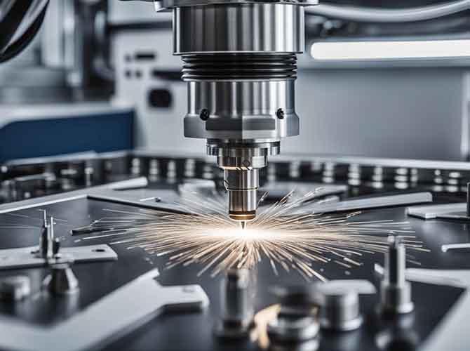
To select the right internal spline broaching tool, we must first establish a clear understanding of the broader tool family. Broaching is a machining process that uses a toothed tool, called a broach, para eliminar material. The main principle involves a series of cutting teeth arranged in order, where each tooth is slightly taller than the one before it. As the broach is pushed or pulled through a workpiece, each tooth removes a small, predetermined amount of material, with the final teeth producing the exact desired shape.
The Primary Division
Broaching is basically divided into two categories based on where the cutting action occurs: internal and external.
Internal broaching is the process of cutting features on an inner surface of a workpiece. This requires a pre-existing hole, either drilled, reamed, or cast, for the tool to pass through. It is the method used to create internal splines, chaveteros, square holes, and other non-circular internal shapes. The internal spline broaching tool is the specialized instrument for this task.
External broaching, for context, cuts features on an outer surface. This includes processes like “slab” broaching to create flat surfaces or “ranura” broaching to cut grooves on a part’s exterior. While it uses the same progressive cutting principle, the tool and machine setup are completely different and are not the focus of this guide.
Focus on Internal Tools
Within the category of internal broaching tools, the primary distinction is based on the direction of force applied during the cut.
Pull-type broaches are the most common design for producing internal splines. As the name suggests, they are pulled completely through the workpiece. This method places the tool body in tension, a state that naturally promotes straightness and stability, reducing the risk of bending. This built-in stability makes pull-type broaches ideal for long lengths of cut and for achieving high-precision results in demanding applications.
Push-type broaches are pushed through the workpiece, placing the tool in compression. Because of this compressive force, they are more likely to buckle and are therefore typically much shorter than pull-type broaches. Their use is generally reserved for shorter lengths of cut, chaveteros, or simple forms, and they are often operated in arbor presses or vertical hydraulic presses.
Specialized Internal Designs
Beyond the basic push-pull classification, several specialized designs offer unique advantages:
Solid broaches are the standard, manufactured from a single, solid piece of tool steel. They are the most common configuration for a wide range of applications.
Shell broaches feature a hollow design where the cutting section, o “shell,” is a separate piece mounted on a reusable arbor. The primary advantage is cost savings in high-volume production. When the cutting teeth wear out, only the shell needs to be replaced, not the entire tool and arbor assembly.
Concentricity broaches are high-precision tools designed to perform two operations in a single pass. They typically broach the spline profile while simultaneously sizing a secondary bore or diameter, ensuring exceptional concentricity between the two features, which is critical in many power transmission components.
Critical Material Considerations
The success or failure of a broaching operation is determined at the interface between the cutting tool and the workpiece. The selection of materials for both is a deeply connected decision that directly impacts tool life, calidad de la pieza, and overall process efficiency. The basic rule is that the broaching tool must be significantly harder, más duro, and more wear-resistant than the material it is cutting, particularly at the elevated temperatures generated in the cutting zone.
Broaching Tool Materials
Choosing a tool material involves a trade-off between hardness (resistance to wear), tenacidad (resistance to chipping and breaking), y costo.
High-Speed Steel (HSS) is the foundation of broach manufacturing.
- M2 Grade HSS is the industry workhorse. It offers a good balance of toughness and affordability, making it the ideal choice for general-purpose broaching of low-to-medium carbon steels, aluminio, latón, and other non-ferrous metals. It typically has a hardness of 62-64 CDH.
- M42 Grade HSS, also known as Cobalt HSS, contains a significant percentage of cobalt (típicamente 8%). This addition dramatically increases “hot hardness,” the material’s ability to retain its hardness at high cutting temperatures. This makes M42 (66-68 CDH) the preferred choice for broaching tougher materials like stainless steels, high-alloy steels, and tool steels.
Powdered Metal (P.M) HSS represents a significant step up in performance. The manufacturing process involves turning molten steel into a powder, which is then consolidated under high pressure and temperature (sintering). This results in a much finer, more uniform carbide structure compared to conventional cast and wrought HSS. The benefit is a superior combination of wear resistance and toughness. PM HSS tools are excellent for high-volume production runs and for machining difficult, abrasivo, or gummy materials like nickel-based superalloys and titanium.
Carbide-Tipped Broaches are specialized tools where individual tungsten carbide inserts serve as the cutting teeth, brazed onto a tough HSS tool body. Carbide is exceptionally hard and wear-resistant but also more brittle than HSS. Its use is reserved for the most demanding applications, such as broaching highly abrasive materials like cast iron or high-silicon aluminum, or for extreme production volumes where maximizing the time between tool changes is the highest priority.
| Material | Características clave | Best For Workpiece Materials | Relative Cost |
| M2 HSS | Good toughness, asequible | Low-carbon steels, aluminio, latón | $ |
| M42 HSS | High hot hardness, buena resistencia al desgaste | Stainless steels, tool steels, high-alloy steels | $$ |
| PM HSS | Excellent wear resistance & tenacidad | Producción de alto volumen, nickel alloys, titanio | $$$ |
| Carburo | Dureza extrema & resistencia al desgaste | Hierro fundido, high-silicon aluminum, compuestos | $$$$ |
The Workpiece Impact
The properties of the workpiece material dictate nearly every aspect of broach design and selection.
Hardness and Tensile Strength are the primary factors. A workpiece with high hardness or tensile strength, such as a pre-hardened 4140 alloy steel at 32 CDH, requires a tool material with superior hot hardness like M42 or PM HSS. For such an application, a typical cutting speed might be around 15-20 feet per minute (FPM). En contraste, a softer 1018 carbon steel could be broached at 25-30 FPM with a standard M2 HSS tool.
Machinability Rating is a measure of how easily a material can be cut. Materials with a low machinability rating, como 316 austenitic stainless steel, son “gummy” and tend to work-harden rapidly during the cut. This requires a broach with very sharp cutting edges, specific cutting geometry, and often a specialized coating to prevent the formation of a built-up edge (BUE), where workpiece material welds itself to the tool face.
Anatomy of a Broach
The geometry of an internal spline broaching tool is complex and precise, with each feature serving a critical function. Understanding this anatomy allows you to specify a tool that is perfectly matched to your spline requirements, workpiece material, and production goals.
The Cutting Section
The performance of a broach is determined by the geometry of its teeth.
The Rise Per Tooth (RPT), also known as chip load, is the most critical design parameter. It is the amount of material each successive tooth removes, typically measured in thousandths of an inch. If the RPT is too high, it generates excessive cutting forces, which can lead to tooth stripping, rotura de herramienta, or machine stalling. If the RPT is too low, the teeth may rub against the workpiece instead of cutting cleanly. This rubbing action generates heat, causes premature dulling, and leads to work hardening of the material and a poor surface finish. A typical RPT for steel is between 0.001″ and 0.003″.
The Face Angle, or Hook Angle, is the angle of the cutting face of the tooth. Its primary function is to curl the chip and direct it into the gullet (the space between teeth). The optimal angle is highly dependent on the workpiece material. Suave, ductile materials like aluminum or low-carbon steel require a higher positive hook angle (p.ej., 12-18 degrees) to effectively shear the material and form a smooth chip. Duro, brittle materials like cast iron require a much lower or even negative hook angle (p.ej., 0-6 degrees) to prevent the cutting edge from chipping.
The Back-Off Angle, or Clearance Angle, is the angle ground onto the top of the tooth behind the cutting edge. Its purpose is to prevent the trailing portion of the tooth from rubbing on the newly machined surface. Insufficient clearance leads to friction, calor, and a poor finish. A typical back-off angle is between 1 y 3 degrees.
Spline Profile Specs
The broach must be ground to the precise specifications of the spline it is intended to produce.
Involute splines are the most common type used in power transmission due to their self-centering properties and excellent strength. When specifying an involute spline broach, you must provide the tool manufacturer with key parameters such as the diametral pitch (or module), pressure angle (p.ej., 30, 37.5, o 45 degrees), numero de dientes, and the desired fit class.
Straight-sided splines have a simpler, non-involute tooth geometry. They are often used for applications where components need to slide axially under load.
A fillet root spline has a curved, rounded profile at the minor diameter, whereas a flat root spline has sharp corners. Fillet root splines are strongly preferred for applications involving high torque or cyclic loading, as the fillet provides superior stress distribution and significantly improves fatigue life compared to the stress concentrations created by a flat root design.
Troubleshooting with Tool Design
Deep expertise is demonstrated not just by knowing the features, but by knowing how to use them to solve real-world problems.
Problema: Mal acabado superficial.
- Likely Causes: Incorrect face or back-off angles for the material, dull teeth, or chip packing in the tooth gullets.
- Tool Design Solution: Ensure the angles are optimized for your workpiece. For materials that produce long, stringy chips (like many steels), specify a tool with chip breakers. These are small, precisely ground notches or grooves in the tooth face or along the cutting edge. They function to break long chips into smaller, more manageable segments, preventing them from packing in the gullets and scoring the finished part surface.
Problema: Galling or Built-Up Edge (BUE).
- Likely Causes: A chemical affinity between the tool and workpiece material, common when machining stainless steels, titanio, and some aluminum alloys. This causes material to weld itself to the cutting edge, leading to a torn surface finish and rapid tool failure.
- Tool Design Solution: The most effective solution is to specify an advanced PVD (Deposición física de vapor) revestimiento. Coatings like Titanium Nitride (Estaño), Titanium Carbonitride (TiCN), or Titanium Aluminum Nitride (TiAlN) create a hard, lubricious barrier between the tool and the workpiece. This low-friction surface reduces the heat of the cut and acts as a chemical barrier, preventing BUE formation and dramatically extending tool life.
Problema: Broach Drifting or Off-Center Splines.
- Likely Causes: Uneven cutting forces caused by inconsistent material or improper tool guidance within the starting bore.
- Tool Design Solution: The tool must be designed with sufficient guidance. This includes a front pilot that fits snugly into the pre-broached hole to align the tool before the first tooth engages, and a rear pilot or shank that is supported at the end of the machine stroke. For high-precision applications where concentricity to another diameter is paramount, the ultimate solution is to specify a concentricity broach.
We encountered a scenario in a high-volume automotive application involving transmission gears made from 4140 steel hardened to 30 CDH. The initial M2 HSS tool was showing severe corner wear on the cutting teeth and failing after only 800 regiones, causing unacceptable levels of downtime. By working with the tool manufacturer, we switched to a new design. The new internal spline broaching tool was made from PM HSS for superior wear resistance and featured a TiAlN coating for better hot hardness and lubricity. We also specified a slightly increased back-off angle of 2.5 degrees to reduce friction. This redesigned tool not only solved the premature wear issue but consistently produced over 3,500 parts before needing a re-sharpen, a 337% increase in tool life that drastically reduced downtime and cost per part.
Ensuring Machine Compatibility
A perfectly designed internal spline broaching tool is useless if it cannot be run on your machine. Verifying compatibility is a critical, non-negotiable step that prevents costly mistakes, daños a la máquina, and project delays. This should be treated as a practical checklist before placing any order.
Matching the Machine
Broaching machines come in several configurations, and the tool must be designed to match.
Vertical vs. Horizontal Machines refers to the orientation of tool travel. Vertical machines are more common and have a smaller footprint, but chip evacuation can sometimes be a challenge. Horizontal machines are very long and require significant floor space, but gravity aids in chip removal, which is beneficial for certain materials.
Pull-Down, Pull-Up, and Push machines describe the tool’s motion relative to the workpiece fixture. A pull-down machine pulls the broach downwards through a stationary part. A pull-up machine pulls it upwards. The tool’s end fitting, known as the pull head, must be designed to interface perfectly with the machine’s specific puller mechanism.
Critical Spec Verification
Before engaging a tool manufacturer, you must know the key specifications of your broaching machine.
Tonelaje (Pulling Force) is the maximum force the machine can exert. The machine must have sufficient tonnage to pull the broach through the material without stalling. The required cutting force is a function of the workpiece material’s shear strength, the length of cut (the number of teeth engaged at one time), and the rise per tooth (RPT). A reputable tool manufacturer can calculate the precise force required for your application and will ensure the tool design does not exceed your machine’s capacity.
Stroke Length is one of the most common and costly oversights. The machine’s available stroke must be significantly longer than the overall length of the broaching tool. This is not just the cutting length; it is the total length from the pull head to the rear pilot. You must account for the tool length plus clearance for loading the workpiece and engaging the puller before the cut begins, as well as clearance to completely exit the part at the end of the stroke.
Holder and Pull Head Compatibility are the physical connection points. The tool’s shank and pull end must match the machine’s fixtures precisely. There are numerous standard and proprietary pull head designs, including threaded ends, keyway slots, and various automatic latching styles. You must provide the exact specifications or drawings of your machine’s puller and rear support to the toolmaker.
Pre-Order Compatibility Checklist:
- [ ] Machine Tonnage: Is it greater than the calculated cutting force?
- [ ] Machine Stroke: Is it greater than the total broach length plus required clearance?
- [ ] Pull Head Type: Does the specified tool pull head match the machine’s puller mechanism?
- [ ] Shank Diameter: Does the tool shank diameter fit the machine’s rear support/holder?
The Financial Equation
When investing in a high-value asset like an internal spline broaching tool, the decision-making process must extend beyond the initial purchase price. Choosing the “cheapest” option is often the most expensive mistake. A strategic evaluation based on Total Cost of Ownership (costo total de propiedad) and long-term performance provides a much clearer path to profitability.
Beyond the Sticker Price
Several factors contribute to the initial cost of a broaching tool:
- Material: There is a clear cost hierarchy, with conventional M2 HSS being the most affordable, followed by M42, then PM HSS, and finally carbide-tipped tools at the premium end.
- Complejidad: The cost increases with the complexity of the geometry. una costumbre, high-precision involute spline profile with multiple chip breakers is significantly more expensive to design and grind than a simple, standard keyway broach.
- Recubrimientos: Advanced PVD coatings like TiAlN add to the upfront cost but provide a substantial return on investment through increased tool life and performance, especially in difficult materials.
- Tamaño: A longer and larger diameter tool requires more raw material, more grinding time, and more complex heat treatment, all of which drive up the price.
Calculating Total Cost
A practical framework for evaluating options is to calculate the Total Cost of Ownership, which focuses on the cost per part produced over the tool’s entire life. The basic formula is:
Cost Per Part = (Initial Tool Cost + Total Re-sharpening Costs) / Total Parts Produced
To perform this analysis, you need to gather key data points:
- Initial Tool Price: The quoted price from the manufacturer.
- Expected Tool Life: The number of parts the tool can produce between sharpenings, and the total number of parts before the tool is scrapped. The manufacturer can provide a reliable estimate based on your application parameters.
- Re-sharpening Cost & Frequency: What is the cost for each re-sharpening service, and how many times can the tool be re-sharpened before it is no longer usable? A typical broach may be sharpened 5 a 15 times.
- Cost of Downtime: This is a critical and often overlooked variable. Calculate the cost per hour of the machine being idle for a tool change. A tool that lasts longer directly reduces this cost.
- Tasa de chatarra: A cheaper, lower-quality tool may produce more out-of-spec parts, leading to a high hidden cost in wasted material and labor.
Consider an illustrative example. A project requires 100,000 regiones.
- Tool A (M2 HSS): Initial cost is $8,000. It produces 2,000 parts per sharpening and can be sharpened 9 times (total life 20,000 regiones). Re-sharpening costs $500 cada. You will need 5 new tools. Total Cost = 5 * ($8,000 + 9 * $500) = $62,500. Cost per part = $0.625.
- Tool B (PM HSS with TiAlN): Initial cost is $12,000. It produces 5,000 parts per sharpening and can be sharpened 9 times (total life 50,000 regiones). Re-sharpening costs $600 cada. You will need 2 new tools. Total Cost = 2 * ($12,000 + 9 * $600) = $34,800. Cost per part = $0.348.
Despite being 50% more expensive upfront, the superior tool results in a 44% lower cost per part and requires 60 fewer tool changes, saving significant downtime. This analysis makes the financially optimal choice clear.
Identifying Quality Manufacturers
Partnering with a reputable manufacturer is as important as the tool’s design itself. These companies possess the engineering expertise, manufacturing capability, and quality control processes to deliver a tool that performs as promised.
The following list represents some of the most established and respected manufacturers in the broaching tool industry. This is not an exhaustive list, and the best partner for your project will depend on your specific technical requirements, location, and service needs. We recommend contacting several manufacturers to find the best fit.
- V W Broaching Service, Inc.
- Known For: A major US-based player known for a wide range of standard and custom broaches, as well as high-volume production broaching services. They have a strong reputation for quality and comprehensive service.
- The Broach Masters, Inc.
- Known For: Specializes in precision gear and spline broaches, with deep expertise in the demanding automotive and aerospace sectors. They are recognized for their engineering capability in complex profiles.
- T.C.G. Broach & Tool Inc.
- Known For: A Canadian manufacturer offering comprehensive design, fabricación, and re-sharpening services. They serve a diverse range of industries and are known for their customer-centric approach.
- Karl Klink GmbH
- Known For: A leading German manufacturer known for high-end broaching machines and tooling. Their name is synonymous with top-tier European engineering, precisión, y rendimiento, particularly in the automotive industry.
- Nachi-Fujikoshi Corp.
- Known For: A major Japanese industrial conglomerate that produces a wide array of high-performance cutting tools. Their broaches are known for exceptional material quality and cutting performance, reflecting Japan’s leadership in tool steel technology.
Making Your Final Decision
Selecting the right internal spline broaching tool is a methodical process, not a guess. The optimal choice is a carefully considered balance of all the factors we have discussed. By moving through the decision-making journey systematically, you can ensure you procure a tool that delivers precision, fiabilidad, and long-term value.
You start with the workpiece to define the tool material. You then carefully specify the spline geometry and performance-enhancing features. Próximo, you confirm absolute compatibility with your machine’s capabilities. Finalmente, you analyze the total cost of ownership, not just the initial purchase price. El “right” tool is not an isolated object; it is a key component in a system that works in harmony with your material, your machine, and your production goals. With this comprehensive approach, you are now equipped to make your final selection with confidence.
Final Selection Checklist:
- [ ] Application Defined: Workpiece material, dureza, and spline specifications are fully documented.
- [ ] Tool Material Selected: The choice (HSS, P.M, Carburo) is justified by the workpiece material and production volume.
- [ ] Tool Design Specified: Rise per tooth, cutting angles, and features like chip breakers or coatings are considered and specified.
- [ ] Machine Compatibility Confirmed: Tonelaje, stroke length, and holder/puller designs are verified.
- [ ] TCO Analyzed: The decision is based on long-term value and cost per part, not just initial price.
- [ ] Quotes Requested: You are fully prepared to engage with reputable manufacturers with a complete set of requirements.