If you’re wondering how to approachcopper machining successfully, la respuesta corta es: priorizar la comprensión de las propiedades físicas únicas del cobre (como alta ductilidad y conductividad térmica), Elija las herramientas y los parámetros de corte adecuados., y abordar problemas comunes como la acumulación de virutas y el desgaste de herramientas de manera proactiva. Ya sea un aficionado que trabaja con piezas pequeñas o un fabricante que produce componentes de gran volumen, copper’s distinct characteristics require tailored strategies—unlike machining harder metals like steel or aluminum. Abajo, we’ll break down everything you need to know to achieve precise, efficient results with copper.
Key Properties of Copper That Impact Machining
Before diving into techniques, it’s critical to grasp why copper behaves differently during machining. Its physical traits directly influence tool selection, velocidades de corte, and surface finish quality. Here’s what you need to know:
- High Ductility: Copper is extremely malleable, meaning it bends and stretches easily instead of breaking cleanly. This leads to long, stringy chips that can clog tools, damage workpieces, or even pose safety risks. Por ejemplo, in a recent project at a precision engineering shop, machinists struggled with chip entanglement when drilling copper fittings—until they adjusted their chip breakers and feed rates.
- Excellent Thermal Conductivity: Copper transfers heat 5x faster than steel and 2x faster than aluminum. While this is a benefit for electrical components, it’s a challenge for machining: heat quickly transfers from the cutting zone to the tool, accelerating wear and reducing tool life. A study by the American Machinist found that tool longevity can drop by 30% when machining copper compared to steel, if heat management isn’t addressed.
- Low Hardness: With a Brinell hardness of 35–45 HB (vs. 120 HB for mild steel), copper is soft and prone to “galling” (material sticking to the tool). This can ruin surface finishes—for instance, a manufacturer of copper electrical connectors noticed scratches on parts until they switched to coated tools and increased cutting speeds.
- Conductividad eléctrica: While not a direct machining challenge, this property means copper parts often require tight tolerances (p.ej., ±0,001 pulgadas) for electrical performance. Machinists must balance speed with precision to avoid dimensional errors.
Common Copper Machining Methods: Ventajas, Contras & Best Uses
Not all machining processes work equally well for copper. Below is a breakdown of the most popular methods, with real-world examples and key considerations to help you choose the right one for your project.
| Machining Method | Mejor para | Ventajas | Contras | Key Tips |
|---|---|---|---|---|
| Molienda | Formas complejas (p.ej., armarios electricos, disipadores de calor) | Versatile for 2D/3D parts; good for high-precision cuts | Risk of chip buildup; requires rigid setups | Utilice acero de alta velocidad (HSS) or carbide end mills; set spindle speeds to 1,500–3,000 RPM for roughing |
| Torneado | Piezas cilíndricas (p.ej., tubería, pernos, casquillos) | Fast for high-volume production; acabados superficiales lisos | Heat can warp thin-walled parts | Use positive-rake inserts to reduce cutting force; apply coolant continuously to dissipate heat |
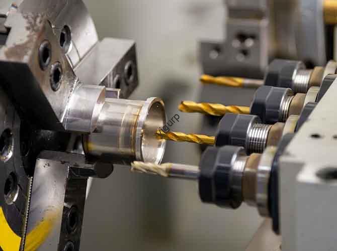
| Perforación | Creando agujeros (p.ej., in circuit boards, accesorios de plomería) | Simple and cost-effective | Chips can get stuck in holes; risk of breakage with small drills | Use twist drills with polished flutes to improve chip evacuation; start with a pilot hole for deep drilling |
| Molienda | Achieving ultra-smooth finishes (p.ej., componentes ópticos, partes medicas) | Produces tight tolerances (±0,0001 pulgadas); elimina rebabas | Slow compared to other methods; generates heat | Use diamond or cubic boron nitride (CBN) ruedas; keep workpiece cool with mist coolant |
Ejemplo del mundo real: A manufacturer of copper heat exchangers switched from conventional milling to high-speed milling (HSM) for their finned parts. By increasing spindle speeds to 4,000 RPM and using carbide tools with TiAlN coatings, they reduced cycle time by 40% and eliminated chip clogging—all while maintaining a surface finish of Ra 0.8 µm (required for heat transfer efficiency).
Essential Tools & Materials for Copper Machining
Choosing the right tools is make-or-break for copper machining. Using tools designed for harder metals will lead to poor results and frequent tool changes. Here’s what you need:
Materiales de herramientas
- Carburo: The most popular choice for copper. herramientas de carburo (p.ej., carburo de tungsteno) resist heat better than HSS and maintain sharp edges longer. Look for grades like WC-Co (tungsten carbide-cobalt) for general use—they offer a balance of hardness and toughness.
- High-Speed Steel (HSS): Suitable for low-volume projects or soft copper alloys (p.ej., cobre puro). HSS is more affordable than carbide but wears faster; it’s best for light cuts (p.ej., finishing passes).
- Coated Tools: Coatings like TiAlN (titanium aluminum nitride) or DLC (carbono tipo diamante) reduce friction and heat. A test by Machinery Lubrication showed that TiAlN-coated carbide tools lasted 50% longer than uncoated tools when machining copper.
Cutting Fluids
Coolant is non-negotiable for copper machining—it cools the tool, lubricates the cutting zone, y tira las virutas. The best options are:
- Soluble Oils: Mix with water (1:10 ratio) para uso general. They’re cost-effective and provide good cooling.
- Synthetic Coolants: Ideal for high-speed machining or parts requiring strict cleanliness (p.ej., componentes electricos). They don’t leave residue and offer better rust protection than soluble oils.
- Cutting Oils: For heavy-duty operations (p.ej., deep drilling). They provide superior lubrication but are messier and more expensive than water-based coolants.
Workholding Equipment
Copper’s softness means it can shift during machining if not held securely. Usar:
- Vise Grips with Soft Jaws: Prevent scratches and distribute pressure evenly (crítico para piezas de paredes delgadas).
- Collares: For turning or milling cylindrical parts—they offer higher concentricity (±0,0005 pulgadas) than chucks.
- Mandriles de vacío: Best for large, flat parts (p.ej., copper sheets) where clamps would block the cutting path.
Step-by-Step Guide to Machining Copper Parts
Follow this practical workflow to avoid common mistakes and ensure consistent results. We’ll use a common project—machining a copper electrical connector—as an example.
1. Prepare the Workpiece
- Select the Right Copper Alloy: Cobre puro (C11000) is soft and hard to machine; para la mayoría de los proyectos, use a brass alloy (p.ej., C36000, “free-machining brass”) which has added zinc to improve chip breaking. For high-heat applications (p.ej., disipadores de calor), use copper-nickel alloys (C71500) para una mejor fuerza.
- Cut to Size: Use a bandsaw to trim the raw copper stock to slightly larger than the final dimensions (add 0.01–0.02 inches for finishing).
- Secure the Workpiece: Mount the stock in a vise with soft jaws. Tighten evenly—over-tightening can deform the copper.
2. Choose Cutting Parameters
Start with these baseline settings (adjust based on your tool and alloy):
- Velocidad del husillo: 1,500–4000 rpm (higher for finishing, lower for roughing).
- Tasa de alimentación: 0.001–0.003 inches per revolution (IPR). Too fast causes tool wear; too slow leads to built-up edge (BUE).
- Profundidad de corte (DOC): 0.01–0.05 inches per pass. Avoid deep cuts—they generate excess heat.
Ejemplo: For milling a C36000 brass connector with a TiAlN-coated carbide end mill:
- Roughing: 2,000 RPM, 0.002 IPR, 0.03 inches DOC
- Refinamiento: 3,500 RPM, 0.001 IPR, 0.005 inches DOC
3. Execute the Machining Process
- Roughing Pass: Remove most of the excess material, focusing on speed over precision. Use a climb milling technique (tool rotates in the same direction as the workpiece feed) to reduce cutting force and chip buildup.
- Finishing Pass: Slow down the feed rate and reduce DOC to achieve the desired surface finish. For the electrical connector, we aimed for Ra 0.4 μm—achieved by making two light finishing passes.
- Monitor Chips: Pause periodically to clear chips. If you see long, stringy chips, increase the feed rate or adjust the chip breaker.
4. Post-Machining Steps
- Deburr: Use a file or deburring tool to remove sharp edges—copper burrs are soft but can cause electrical shorts in connectors.
- Limpio: Wipe the part with a solvent (p.ej., isopropyl alcohol) to remove coolant residue. Para piezas eléctricas, use ultrasonic cleaning to ensure no debris remains.
- Inspect: Check dimensions with calipers or a micrometer. For the connector, we verified the hole diameter (0.125 ± 0.001 pulgadas) and thread depth (0.25 pulgadas) to meet specs.
Common Copper Machining Challenges & How to Fix Them
Even experienced machinists run into issues with copper. Below are the most frequent problems and actionable solutions, backed by industry data.
1. Built-Up Edge (BUE)
What it is: Copper sticks to the tool’s cutting edge, forming a “buildup” that ruins surface finishes and increases tool wear.Why it happens: Low cutting speeds, high feed rates, or dull tools. A survey byMecanizado de precisión found that BUE occurs in 60% of copper machining projects when speeds are below 1,000 RPM.Fix:
- Increase spindle speed by 20–30%.
- Use a coated tool (TiAlN or DLC) para reducir la fricción.
- Apply more coolant to the cutting zone.
2. Chip Clogging
What it is: Largo, flexible chips get stuck in tool flutes or between the tool and workpiece.Why it happens: Copper’s ductility; improper chip breaker design.Fix:
- Use tools with spiral flutes (for drilling/milling) or positive-rake inserts (for turning) to break chips into smaller pieces.
- Increase feed rate slightly (p.ej., de 0.001 a 0.002 IPR) to encourage chip breaking.
- Use a chip evacuation system (p.ej., air blowers or coolant jets) for high-volume jobs.
3. Tool Wear
What it is: Tools dull quickly, leading to poor precision and increased cycle time.Why it happens: Copper’s thermal conductivity transfers heat to the tool; soft material causes abrasion.Fix:
- Use carbide tools instead of HSS (carbide resists heat better).
- Reduce DOC to 0.01–0.03 inches per pass to lower heat generation.
- Replace tools at the first sign of wear (p.ej., visible edge rounding)—don’t wait for poor finishes.
4. Workpiece Deformation
What it is: Soft copper bends or warps during machining, especially thin-walled parts.Why it happens: Excess cutting force, uneven clamping, or heat.Fix:
- Use a lighter feed rate (0.001 IPR or lower) to reduce force.
- Secure the workpiece with multiple clamps or a vacuum chuck to distribute pressure.
- Use mist coolant (instead of flood coolant) to cool without adding weight to thin parts.
Yigu Technology’s Perspective on Copper Machining
En Yigu Tecnología, we’ve worked with copper for over a decade—designing machining solutions for industries ranging from electronics to aerospace. Our key insight? Copper machining isn’t about “fighting” its properties—it’s about leveraging them. Por ejemplo, we recently helped an EV battery manufacturer optimize their copper busbar machining: by switching to our custom carbide tools with variable helix flutes and adjusting speeds to 3,200 RPM, they cut tool changes by 45% and improved part consistency. We also emphasize sustainability: using high-efficiency coolants and recycling copper chips (which retain 95% of their value) reduces waste and costs. Ultimately, successful copper machining combines the right tools, data-driven parameters, and a willingness to adapt—traits we prioritize in every project.
FAQ About Copper Machining
1. What’s the difference between machining pure copper and copper alloys?
Cobre puro (C11000) is softer and more ductile, making it prone to BUE and chip clogging. Alloys like brass (C36000) o bronce (C93200) have added metals (zinc, estaño) that increase hardness and improve machinability. For most projects, alloys are easier to work with—save pure copper for applications where high electrical conductivity is critical (p.ej., electrical wires).
2. Can I use the same tools for copper and aluminum?
While both are soft metals, copper’s higher thermal conductivity means you need more heat-resistant tools. For aluminum, HSS tools work well; para cobre, carbide or coated tools are better. You’ll also need to adjust speeds: copper requires lower RPM than aluminum (p.ej., 2,000 RPM for copper vs. 3,000 RPM for aluminum with the same tool).
3. How do I achieve a mirror finish on copper parts?
Start with a smooth machining finish (Real academia de bellas artes 0.2 μm or lower) using a fine-cutting tool. Entonces, polish the part with a buffing wheel and a polishing compound (p.ej., colorete). For ultra-high gloss (p.ej., piezas decorativas), follow with a final pass using a diamond paste (1–3 μm grit).
4. Is dry machining possible with copper?
It’s not recommended for most projects. Dry machining increases heat, leading to faster tool wear and BUE. Sin embargo, para pequeños, piezas simples (p.ej., a copper washer), you can try dry machining with a DLC-coated tool and low feed rates—just monitor the tool closely for wear.
5. What tolerances can I achieve with copper machining?
With proper tools and setups, you can achieve tolerances as tight as ±0.0001 inches (molienda) or ±0.001 inches (fresado/torneado). Para componentes eléctricos (p.ej., conectores), aim for ±0.0005 inches to ensure proper fit and conductivity.